SuperElevationCurve
Description
The SuperElevationCurve object represents the road banking
angle (superelevation) profile as a function of distance along a road.
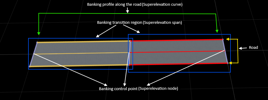
A superelevation curve is an ordered collection of control points, called superelevation
nodes, connected by spans that define how the banking angle varies continuously with distance
along the road center line. Each node specifies a banking angle at a specific distance along
the road, while each span interpolates between two adjacent nodes to create a smooth banking
transition. Every RoadRunner road automatically contains a
SuperElevationCurve object with default nodes at the start and end of the
road. By inserting additional nodes or updating existing ones, you can define uniform or
non-uniform banking for straight or curved roads. The SuperElevationCurve
object works independently of road geometry and applies consistently to both straight and
circular road segments.
Creation
To retrieve a SuperElevationCurve object, extract the
SuperElevationCurve property of a road in your RoadRunner scene. Every
road contains a SuperElevationCurve that defines how the road banking
varies along its length. For example, given a Road object, rrRoad, the expression seCurve =
rrRoad.SuperElevationCurve returns the SuperElevationCurve
object seCurve associated with that road.
By default, the SuperElevationCurve contains two nodes: one at the
start of the road (distance = 0) and one at the end of the road (distance = total length of
the road). You can insert additional nodes at intermediate distances to define non-uniform
banking for straight or curved roads. RoadRunner creates and manages the
SuperElevationCurve of a road automatically, you cannot delete it, but
you can modify it by updating or inserting nodes.
Properties
Object Functions
insertNode | Insert node in span sequence |
Examples
Create a roadrunner object, specifying the path to an existing project. For example,
this code shows the path to a project, on a Windows® machine, located at "C:\RR\MyProject". This code assumes
that RoadRunner is installed in the default location, and returns an object,
rrApp, that provides functions for performing basic tasks such as
opening, closing, and saving scenes and projects.
rrApp = roadrunner(ProjectFolder="C:\RR\MyProject");newScene function, specifying the roadrunner object rrApp.
newScene(rrApp)
Create a RoadRunner authoring API object, rrAPi, that references the object
for the current RoadRunner instance rrApp. The rrApi object
enables you to programmatically author scenes, such as by adding and modifying road and
lane components, using MATLAB®.
rrApi = roadrunnerAPI(rrApp);
Extract the object for your scene from the Scene property of the authoring API object
rrApi. The extracted Scene object enables you to
specify the scene in which to add scene components, such as roads and lanes.
scn = rrApi.Scene;
Extract the object for your RoadRunner project from the Project property of the authoring API object
rrApi. The extracted Project object enables you
to specify the project folder for the current RoadRunner session from which to retrieve asset objects. You can use the asset
objects to add lane markings to the lanes in your
scene.
prj = rrApi.Project;
Use the addClothoidFitRoad function to add a new road.
Specify the position of the road by specifying the positions of its start point
startPt and end point
endPt.
startPt = [0 0 0]; endPt = [50 0 0]; rrRoad = addClothoidFitRoad(scn,[startPt; endPt]);
Extract the reference lane from the ReferenceLane property of the road
rrRoad. The extracted property ReferenceLane
defines the center line of the
road.
refLane = rrRoad.ReferenceLane;
Use the extracted refLane object to add lanes on either side of
the reference lane of the road using the addLaneToLeft and addLaneToRight
functions.
leftLane = addLaneToLeft(refLane); rightLane = addLaneToRight(refLane);
Use the getAsset function to retrieve the LaneMarkingStyle objects for a dashed solid yellow
lane marking. These objects define the lane marking assets used to mark the spans in the
lane marking profile of the reference
lane.
dashedWhiteMarkingStyle = prj.getAsset("<PROJECT>/Assets/Markings/DashedSingleWhite.rrlms","LaneMarkingStyle"); solidWhiteMarkingStyle = prj.getAsset("<PROJECT>/Assets/Markings/SolidSingleWhite.rrlms","LaneMarkingStyle");
Mark the boundaries of the lanes.
leftLaneSpan = leftLane.LaneMarkingProfile.Spans(1); leftLaneSpan.LaneMarkingStyle = solidWhiteMarkingStyle; rightLaneSpan = rightLane.LaneMarkingProfile.Spans(1); rightLaneSpan.LaneMarkingStyle = solidWhiteMarkingStyle; referenceLaneSpan = refLane.LaneMarkingProfile.Spans(1); referenceLaneSpan.LaneMarkingStyle = dashedWhiteMarkingStyle;
Access the superelevation definition of the road by extracting its
SuperElevationCurve
property.
seCurve = rrRoad.SuperElevationCurve;
Inspect the default superelevation nodes of the road. By default, the
SuperElevationCurve contains two nodes: one at the start of the
road and one at the end of the
road.
nodes = seCurve.Nodes
Apply Uniform Banking Along Entire Road
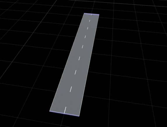
Set the same banking angle at the start and end nodes to apply uniform banking along the full road length.
nodes(1).Angle = 10;
nodes(end).Angle = 10;
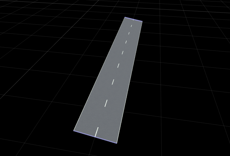
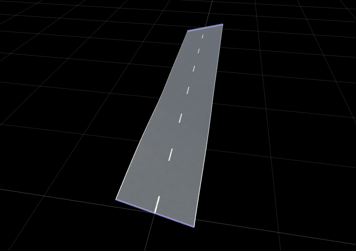
Define Non-Uniform Banking Using Start and End Nodes
Assign different banking angles at the start and end of the road to create a continuous banking transition.
nodes(1).Angle = 15;
nodes(end).Angle = -15;
You can also use the addSuperElevation function to define different
banking angles at the start and end of the
road.
addSuperElevation(rrRoad,0,15)   % 0 indicates the start position of the road
addSuperElevation(rrRoad,50,-15) % 50 indicates the end position of the road
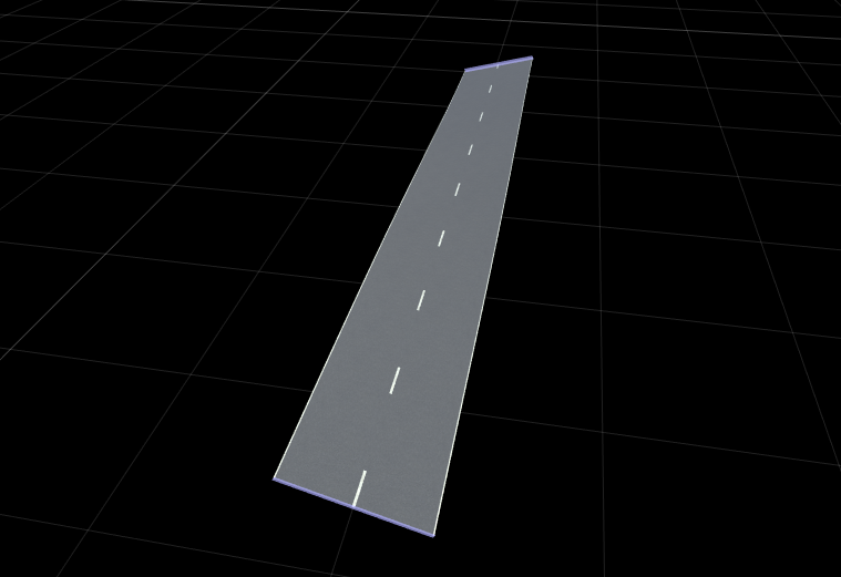
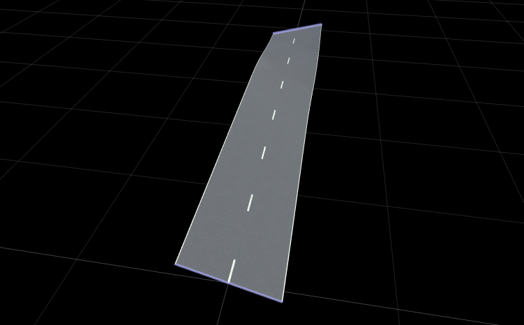
Insert Intermediate Superelevation Nodes
Insert a new superelevation control point at a specified distance along the road.
midNode = insertNode(seCurve,25);
midNode.Angle = -10;
Insert another superelevation node between the start node and your new midpoint node.
addSuperElevation(rrRoad,12,-10);
Modify Existing Superelevation Node
Update the banking angle of an existing node without inserting a new one.
midNode.Angle = 20;
Version History
Introduced in R2026a
See Also
SuperElevationNode | SuperElevationSpan | addSuperElevation | insertNode