Traffic Light Negotiation Using Vehicle-to-Everything Communication
This example shows how to model and simulate a traffic light negotiation application using vehicle-to-everything (V2X) communication. This example uses the vehicle-to-vehicle (V2V) and vehicle-to-infrastructure (V2I) modes of V2X communication.
Introduction
A traffic light negotiation system makes an appropriate decision at an intersection based on the current state of the traffic light and the status of other surrounding vehicles. V2V and V2I are wireless communication technologies that transmit essential information about the states of other vehicles and the state of a traffic light signal to an ego vehicle. The V2V and V2I technologies improve the perceptual ability of vehicles, enabling them to effectively manage traffic light negotiation. The information received through the V2V and V2I systems is used by the decision logic component of an automated driving application. The decision logic component reacts to this information regarding the state of the traffic light and surrounding vehicles and provides necessary inputs to the controller to guide the vehicle safely.
This example builds on the Traffic Light Negotiation example. The traffic light negotiation example shows how to design and test decision logic for negotiating a traffic light at an intersection using probabilistic vision and radar sensors. This example shows how to design and test decision logic, using V2V and V2I communication, for negotiating a traffic light while preventing collisions at intersections.
In this example, you:
Explore the test bench model — The model contains components for the traffic light sensors and environment, V2V communication, V2I communication, tracker, decision logic, controls, and vehicle dynamics.
Model V2V and V2I communication — The model uses V2V mode to communicate basic safety messages (BSMs) from non-ego vehicles to the ego vehicle. V2I mode communicates signal phase and timing (SPAT) messages from the traffic signal to the ego vehicle. For more details on V2V communication, see Intersection Movement Assist Using Vehicle-to-Vehicle Communication.
Model the decision logic — The decision logic identifies the most important object (MIO) and the state of the traffic signal of interest and arbitrates between them. It provides a reference path for the ego vehicle to follow at an intersection in the absence of lane markings. The decision logic subsystem also differentiates between a lead vehicle and a crossover vehicle, to provide crossover vehicle alert.
Simulate interactions with traffic light — Configure the model to test the interactions between the decision logic and controls of the ego vehicle while approaching a signalized intersection in the presence of a lead vehicle.
Simulate the interactions with a crossover vehicle and traffic light — Configure the model to test the interactions between the traffic light decision logic and controls of the ego vehicle when there is cross traffic at the intersection.
Explore other scenarios — These scenarios test the system under additional conditions.
Explore Test Bench Model
To explore the test bench model, load the traffic light negotiation with V2X project.
openProject("TrafficLightNegotiationWithV2X");
To explore the behavior of the traffic light negotiation system, open the simulation test bench model for the system.
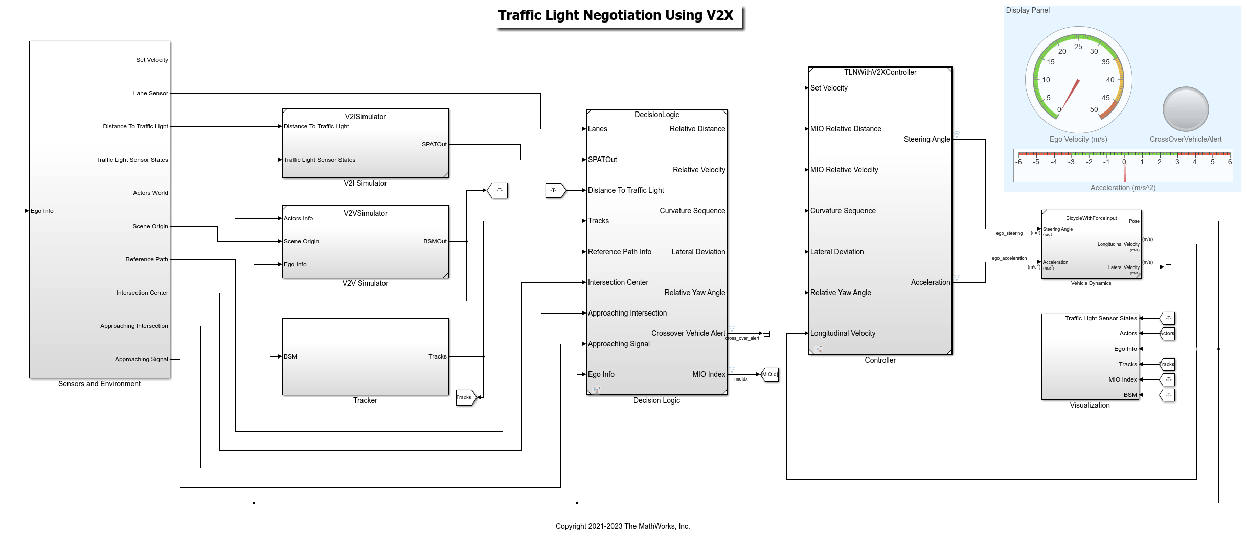
open_system("TrafficLightNegotiationWithV2XTestBench");
Opening this model runs the helperSLTrafficLightNegotiationWithV2XSetup function that initializes the scenario using the drivingScenario object in the base workspace. The function runs the default scenario, scenario_03_TLNWithV2X_Straight_With_Lead_and_CrossOver, which contains an ego vehicle with a lead vehicle and crossover vehicle. This function also loads the V2XChannelInfo.mat file, provided by this example, to save the precomputed channel characteristics to the base workspace for the range specified. The setup function configures the controller design parameters, vehicle model parameters, and Simulink® bus signals required for defining the inputs and outputs for the TrafficLightNegotiationWithV2XTestBench model.
The test bench model contains these subsystems:
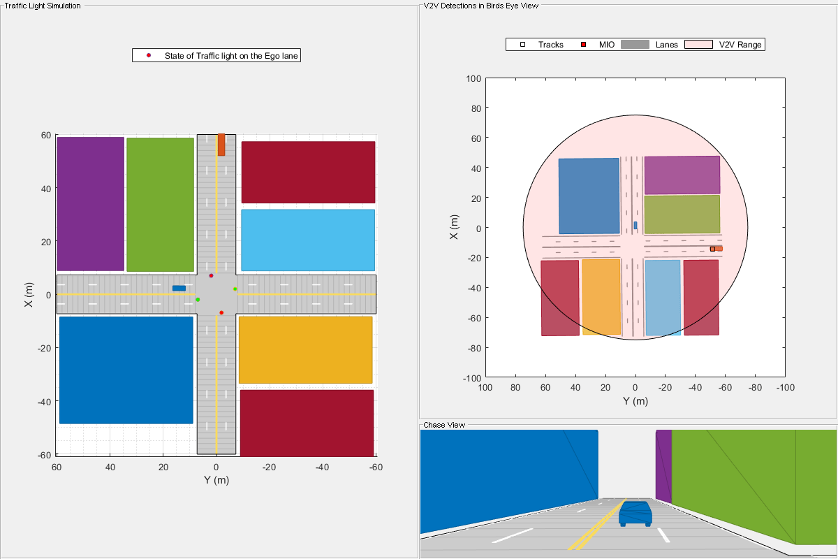
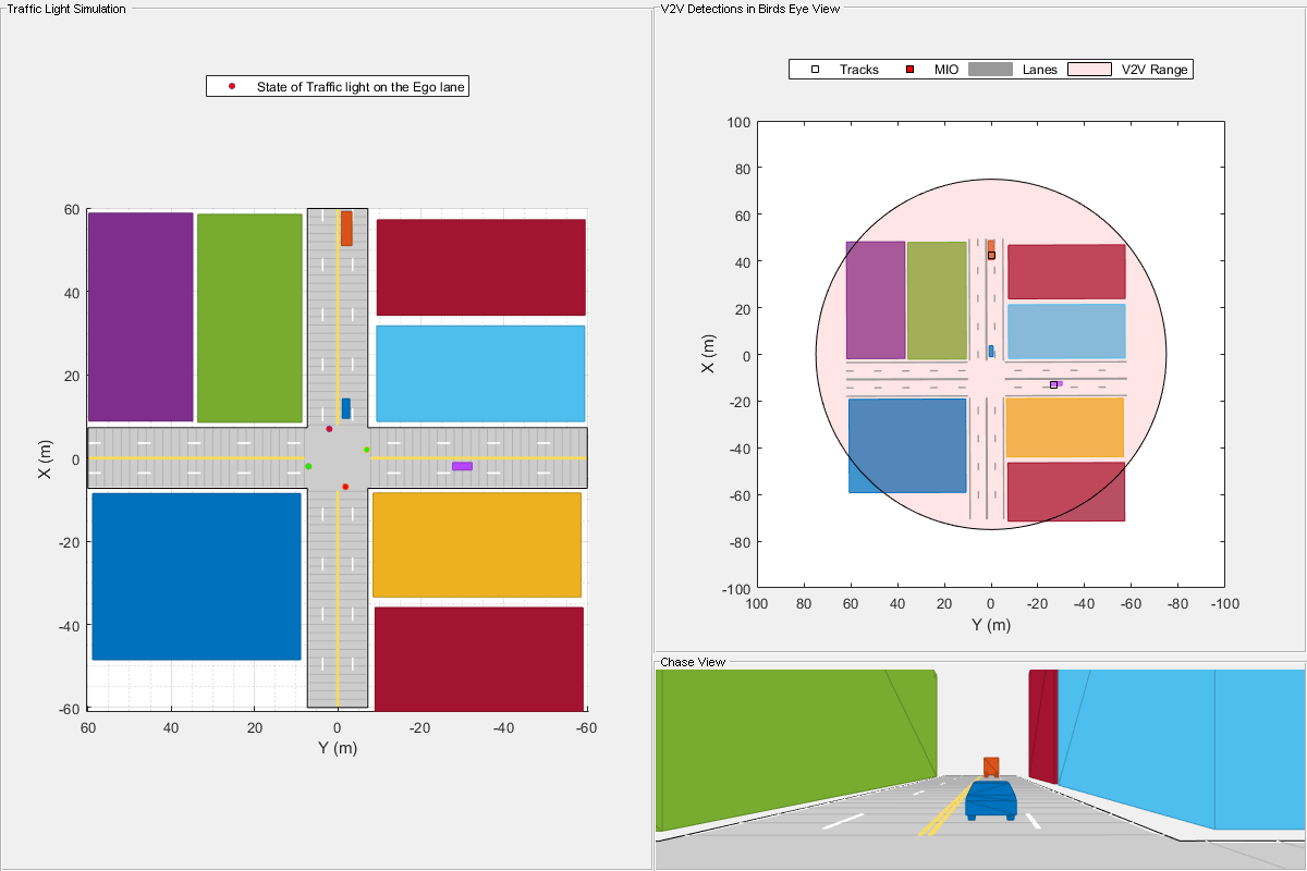
Sensors and Environment— Models the traffic light sensors, road network, vehicles, and the camera and radar sensors used for simulation.V2V Simulator— Models the vehicle-to-vehicle (V2V) communication system.V2I Simulator— Models the vehicle-to-infrastructure (V2I) communication system.Tracker— Converts received BSMs into detections, and tracks each detection using a Multi-Object Tracker.Decision Logic— Arbitrates between the traffic light and other lead vehicles or crossover vehicles at the intersection.Controller— Generates longitudinal and lateral controls using Path Following Control System (Model Predictive Control Toolbox) block andWatchdog Braking Controllersubsystem.Vehicle Dynamics— Models the ego vehicle using a Bicycle Model block, and updates its state using commands received from theControllerreference model.Visualization— Plots the world coordinate view of the road network, vehicles, and the traffic light state during simulation.
This example reuses the Vehicle Dynamics subsystem from the Highway Lane Following example. This example focuses on the V2V Simulator and V2I Simulator subsystems and Decision Logic reference model.
The Sensors and Environment subsystem configures the road network, defines target vehicle trajectories, and provides scenario-related information. Open the Sensors and Environment subsystem.
open_system("TrafficLightNegotiationWithV2XTestBench/Sensors and Environment");

The Sensors and Environment subsystem consists of these sections:
Scenario and Actors— Configures the scenario and actors. The Scenario Reader block takes the ego vehicle information as input to perform closed-loop simulation. It outputs ground truth information for the lanes and actors in ego vehicle coordinates. This block reads thedrivingScenarioobject,scenario, which contains a road network compatible with theTrafficLightNegotiationWithV2XTestBenchmodel, from the base workspace. This section also converts the actor poses from the coordinates of the ego vehicle to world coordinates using a Vehicle To World block.Traffic Light Sensor Simulation— Simulates the traffic lights using four traffic light sensors at an intersection. For more information, see the Traffic Light Negotiation example.Scenario Information— Provides scenario-related information such as reference path, scene origin, approaching intersection, signal name, set velocity for the ego vehicle, and intersection center information.
Model V2V and V2I Communication
The V2V Simulator represents the message-based communication between vehicles present in the scenario. Each vehicle transmits essential information about its state in the form of BSMs. The V2I Simulator represents the message-based communication between the ego vehicle and infrastructure. In this example, the infrastructure is a traffic light sensor that transmits SPAT messages.
V2V Simulator
The V2V Simulator subsystem consists of the V2V Transmitter and V2V Receiver subsystems.
Open the V2V Simulator subsystem.
open_system("TrafficLightNegotiationWithV2XTestBench/V2V Simulator")
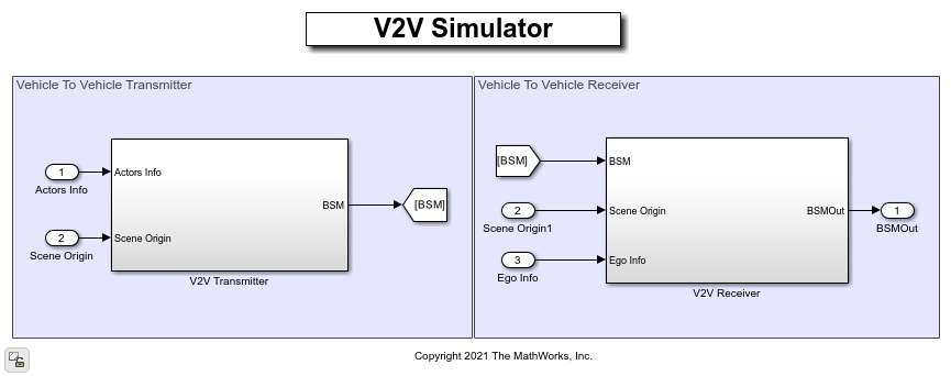
The V2V Transmitter subsystem implements the transmitters of all target vehicles in the scenario using the HelperV2VTransmitter object and uses the actor information and the scene origin information to generate BSMs. First, the subsystem passes the input actor information through an inertial navigation system (INS) and global navigation satellite system (GNSS) to apply noise to the input data. Then, it converts the target vehicle poses from Cartesian coordinates to geographic coordinates to generate the BSMs. To convert the generated BSMs to Simulink messages, the subsystem uses a Send block.
A generated BSM contains these attributes for each vehicle:
MsgCount— Sequence number for a stream of messages.TemporaryId— Random device identifier.DSecond— Time at which the position was determined.Latitude— Geographic latitude of the vehicle.Longitude— Geographic longitude of the vehicle.Elevation— Geographic position of the vehicle above or below the reference ellipsoid.PositionalAccuracy— Accuracy of the positional determination.TransmissionState— The current state of the vehicle transmission.Speed— Speed of the vehicle.Heading— Current heading of the vehicle, in degrees clockwise from north.SteeringWheelAngle— Angle of the steering wheel of the vehicle.AccelerationSet4Way— Acceleration of the vehicle along three directions, and the yaw rotation rate.BrakeSystemStatus— Current brake and system control status.VehicleSize— Length and width of the vehicle.
In the V2V Receiver subsystem, a Receive block converts the BSMs back to a signal. The V2V Receiver subsystem implements the receiver behavior for the ego vehicle using the HelperV2VReceiver object, and takes the BSM, ego information, and scene origin as input. The V2V Receiver uses precomputed channel characteristics to receive the message. The channel characteristics provide the throughput percentage for a given distance between the transmitter and receiver. If the throughput percentage is greater than the generated random number, then the subsystem receives the BSM and appends it to the output bus BSMOut. For more details on channel characteristics, see Intersection Movement Assist Using Vehicle-to-Vehicle Communication.
V2I Simulator
The V2I Simulator subsystem consists of the V2I Transmitter and V2I Receiver subsystems.
Open the V2I Simulator subsystem.
open_system("TrafficLightNegotiationWithV2XTestBench/V2I Simulator")
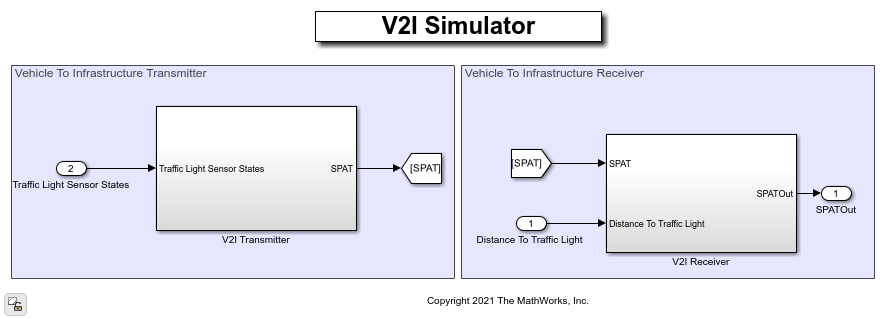
The V2I Transmitter subsystem implements the transmitter of a traffic light sensor using the HelperV2ITransmitter object, and generates the SPAT message for the traffic light sensor. The SPAT message conveys the current status of one or more signalized intersections in a region. To convert the generated SPATs to a Simulink messages, the subsystem uses a Send block.
A generated SPAT contains these attributes:
TimeStamp— Minute of the year.Name— Region name.Intersection— Traffic signal information for each intersection in a region.
In the V2I Receiver subsystem, a Receive block converts the SPAT messages back to a signal. The V2I Receiver subsystem implements the receiver behavior for the ego vehicle using the HelperV2IReceiver object. The V2I Receiver uses precomputed channel characteristics. For a specified distance between the transmitter and receiver, if the throughput is greater than the preset threshold, the receiver receives the SPAT message sent by the transmitter.
Model Decision Logic
The Decision Logic reference model arbitrates between the lead vehicle, a crossover vehicle, and the traffic light. The model computes the relative velocity and relative distance of the ego vehicle with respect to the MIO. The model also computes the curvature, relative yaw angle, and lateral deviation from the reference path.
Open the Decision Logic reference model.
open_system("DecisionLogic");

The Find MIO MATLAB Function block finds the MIO from the input object tracks. The MIO can be a lead car in the current lane, or it can be a crossover vehicle that can possibly collide with the ego vehicle. The block provides the relative distance and relative velocity of the ego vehicle, with respect to the MIO. For crossover vehicles, the relative distance is the distance between the ego vehicle and the estimated collision point. The relative velocity is the ego velocity towards the estimated collision point. When no MIO is present, this block sets both the relative velocity and relative distance to infinity.
The HelperCalculateReferencePose MATLAB System object™ computes the curvature, relative yaw angle, and lateral deviation from the reference path. The Arbitration Logic block, which arbitrates between the MIO and the traffic light, is reused from the Traffic Light Decision Logic reference model in the Traffic Light Negotiation example.
Simulate Interactions with Traffic Light
Configure the model to use the scenario_01_TLNWithV2X_LeftTurn_With_Lead scenario.
helperSLTrafficLightNegotiationWithV2XSetup(ScenarioFcnName="scenario_01_TLNWithV2X_LeftTurn_With_Lead");
To reduce Command Window output, turn off the model predictive control (MPC) update messages.
mpcverbosity("off");
In this test scenario, a lead vehicle travels in the ego lane and crosses the intersection while the traffic light is green. Then, the traffic light turns red forcing the ego vehicle to wait. The ego vehicle is expected to follow the lead vehicle, negotiate the traffic light, and make a left turn.
Simulate the test bench model.
sim("TrafficLightNegotiationWithV2XTestBench");
You can plot the results using the helperTLNWithV2XResults function.
helperTLNWithV2XResults(logsout)
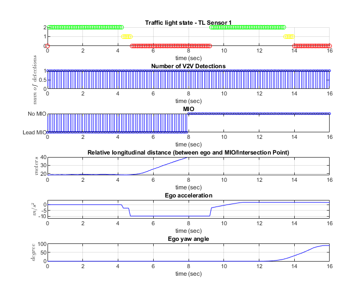
The
Traffic light state - TL Sensor 1plot shows the traffic light sensor states ofTL Sensor 1. It changes from green to yellow, then from yellow to red, and then repeats this behavior.The
Number of V2V Detectionsplots shows the number of vehicles detected using V2V communication. Observe that the only non-ego vehicle present in the scenario is detected most of the time.The
MIOplot shows the type of MIO at each time instant. Notice that the MIO is initially the lead vehicle, and after the ego vehicle takes the left turn, there is no MIO as there is no lead vehicle or crossover vehicle.The
Ego accelerationplot shows the acceleration profile from theController. Notice that the ego vehicle decelerates slightly more than 4 seconds into the simulation, to react to the red state of the traffic light. When the traffic light turns green, slightly more than 9 seconds into the simulation, the ego vehicle accelerates.The
Ego yaw angleplot shows the yaw angle profile of the ego vehicle. Notice that the yaw angle is close to 0 degrees up to 12 seconds into the simulation because the ego vehicle travels straight while approaching the intersection. When the ego vehicle takes a left turn through the intersection, slightly more than 12 seconds into the simulation, the ego yaw angle shows significant variation.
Simulate Interactions with Crossover Vehicle and Traffic Light
Configure the model to use the scenario_03_TLNWithV2X_Straight_With_Lead_and_CrossOver scenario.
helperSLTrafficLightNegotiationWithV2XSetup(ScenarioFcnName="scenario_03_TLNWithV2X_Straight_With_Lead_and_CrossOver");
This test scenario configures the model to test the interactions between the decision logic and controls of the ego vehicle when both a lead vehicle and a cross-traffic vehicle are present at the intersection. The ego vehicle is expected to follow the lead vehicle, wait for the crossover vehicle to clear the intersection, and negotiate the traffic light.
Simulate the test bench model.
sim("TrafficLightNegotiationWithV2XTestBench");
Plot the results.
helperTLNWithV2XResults(logsout)
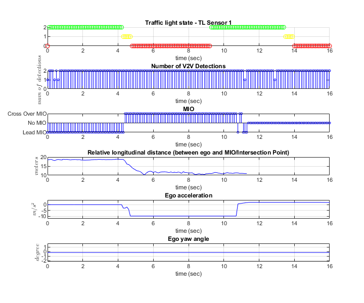
The ego begins to decelerate slightly more than 4 seconds into the simulation, in response to detecting the red traffic light. The ego vehicle halts at the intersection. While waiting at the intersection, the crossover vehicle approaches the intersection and becomes the MIO, as shown in the MIO plot, slightly more than 4 seconds into the simulation. Though the light turns green slightly more than 9 seconds into the simulation, the ego vehicle does not accelerate until the crossover vehicle moves out of the intersection. After 10 seconds, the ego vehicle starts accelerating and moves through the intersection. Because the ego vehicle drives straight throughout the simulation, the ego yaw angle does not change.
Explore Other Scenarios
The example provides these additional scenarios that are compatible with the TrafficLightNegotiationWithV2XTestBench model.
scenario_01_TLNWithV2X_LeftTurn_With_Leadscenario_02_TLNWithV2X_LeftTurn_With_CrossOverscenario_03_TLNWithV2X_Straight_With_Lead_and_CrossOver(default)scenario_04_TLNWithV2X_Straight_With_SequenceOfCrossOverscenario_05_TLNWithV2X_Straight_With_CrossOver_SlowingToStop
For more details on each scenario, view the comments in its file. You can configure the Simulink model and workspace to simulate these scenarios using the helperSLTrafficLightNegotiationWithV2XSetup function.
helperSLTrafficLightNegotiationWithV2XSetup(ScenarioFcnName="scenario_02_TLNWithV2X_LeftTurn_With_CrossOver");
Enable the MPC update messages once again.
mpcverbosity("on");
References
[1] SAE International. Dedicated Short Range Communications (DSRC) Message Set Dictionary. J2735_201603. SAE International, issued September 2015; revised March 2016. https://www.sae.org/standards/content/j2735_201603/.
See Also
Blocks
Topics
- Traffic Light Negotiation
- Traffic Light Negotiation with Unreal Engine Visualization
- Intersection Movement Assist Using Vehicle-to-Vehicle Communication
- Highway Lane Change
- Highway Lane Following
- Autonomous Emergency Braking with High-Fidelity Vehicle Dynamics
- Forward Collision Warning Using Sensor Fusion