Traffic Light Negotiation with Unreal Engine Visualization
This example shows how to design and simulate a vehicle to negotiate traffic lights in the Unreal Engine® driving simulation environment.
Introduction
Decision logic for negotiating traffic lights is a fundamental component of automated driving applications. The decision logic interacts with a controller to steer the ego vehicle based on the state of the traffic light and other vehicles in the ego lane. Simulating real-world traffic scenarios with realistic conditions can provide more insight into the interactions between the decision logic and the controller. Automated Driving Toolbox™ provides a 3D simulation environment powered by Unreal Engine® from Epic Games®. You can use this engine to visualize the motion of a vehicle in a prebuilt 3D scene. This engine provides an intuitive way to analyze the performance of decision logic and control algorithms when negotiating a traffic light at an intersection.
For information on how to design the decision logic and controls for negotiating traffic lights in a cuboid environment, see the Traffic Light Negotiation example. This example shows how to control a traffic light in an Unreal scene and then how to simulate and visualize vehicle behavior for different test scenarios. In this example, you will:
Explore the architecture of the test bench model: The model contains sensors and environment, traffic light decision logic, controls, and vehicle dynamics.
Control traffic light in an Unreal scene: The
Simulation3DTrafficLightControllerhelper block configures the model to control the state of a traffic light in an Unreal scene by using Simulink®.Simulate vehicle behavior during green to red transition: The model analyzes the interactions between the decision logic and the controller when the traffic light state transitions from green to red and the ego vehicle is at a distance of 10 meters from the stop line.
Simulate vehicle behavior during red to green transition: The model analyzes the interactions between the decision logic and the controller when the traffic light transitions from red to green and the ego vehicle is at a distance of 11 meters from stop line. In this case, the ego vehicle also negotiates traffic light as another vehicle crosses the intersection.
Explore other scenarios: These scenarios test the system under additional conditions.
You can apply the modeling patterns used in this example to test your own decision logic and controls to negotiate traffic lights in an Unreal scene.
This example requires a Window® 64-bit platform.
if ~ispc
    error(['This example is only supported on Microsoft', ...
        char(174), ' Windows', char(174), '.']);
end
Explore Architecture of Test Bench Model
To explore the test bench model, load the traffic light negotiation with unreal project.
openProject("TLNUnreal");
To explore the behavior of the traffic light negotiation system, open the simulation test bench model for the system.
open_system("TLNWithUnrealTestBench");
Opening this model runs the helperSLTrafficLightNegotiationWithUnrealSetup script to initialize the test scenario stored as a drivingScenario object in the base workspace. The default test scenario, scenario_03_TLN_straight_greenToRed_with_lead_vehicle, contains one ego vehicle and two non-ego vehicles. This setup script also configures the controller design parameters, vehicle model parameters, and Simulink® bus signals to define the inputs and outputs for the TLNWithUnrealTestBench model.
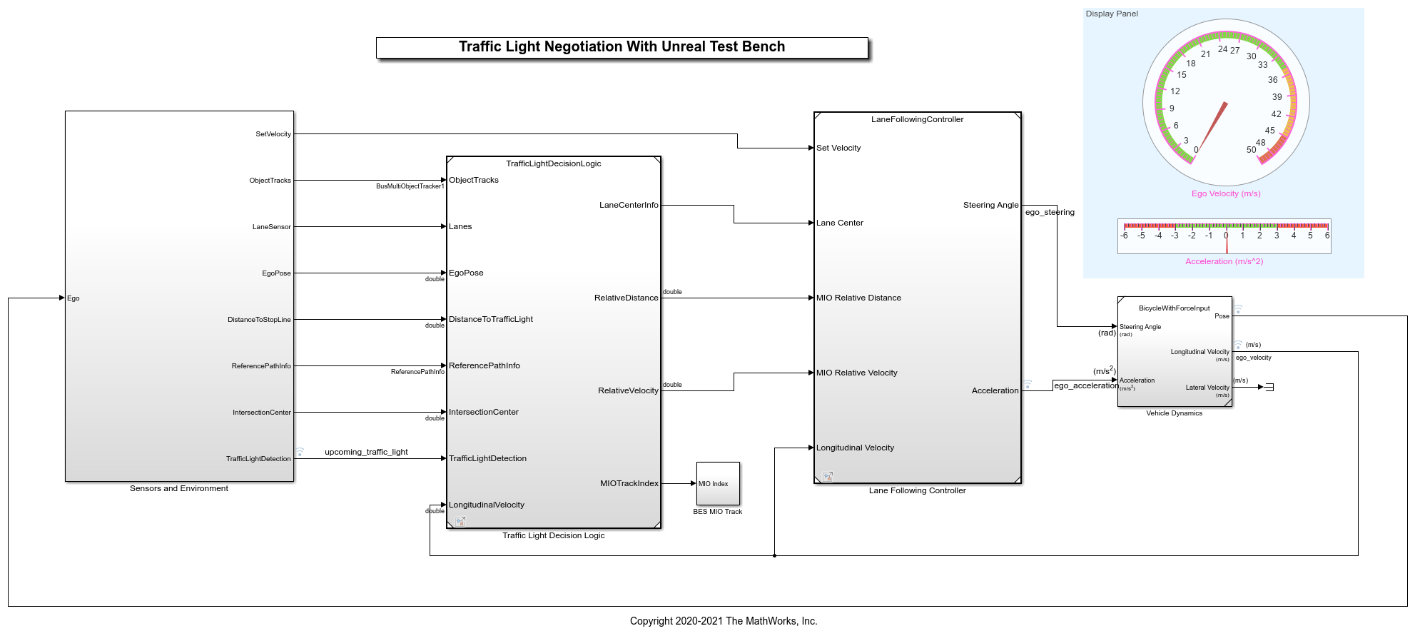
The test bench model contains the following subsystems:
Sensors and Environment: Models the road network, vehicles, camera, and radar sensors used for simulation. The subsystem uses the
Simulation3DTrafficLightControllerhelper block to control the state of traffic lights in an Unreal scene.Traffic Light Decision Logic: Arbitrates between the traffic light and other lead vehicles or cross-traffic vehicles at the intersection.
Lane-Following Controller: Generates longitudinal and lateral controls for the ego vehicle.
Vehicle Dynamics: Models the ego vehicle using a Bicycle Model block and updates its state using commands received from the Lane Following Controller reference model.
The Traffic Light Decision Logic, Lane Following Controller reference models, and Vehicle Dynamics subsystem are reused from the Traffic Light Negotiation example. This example modifies the Sensors and Environment subsystem to make it compatible for simulation with an Unreal scene.
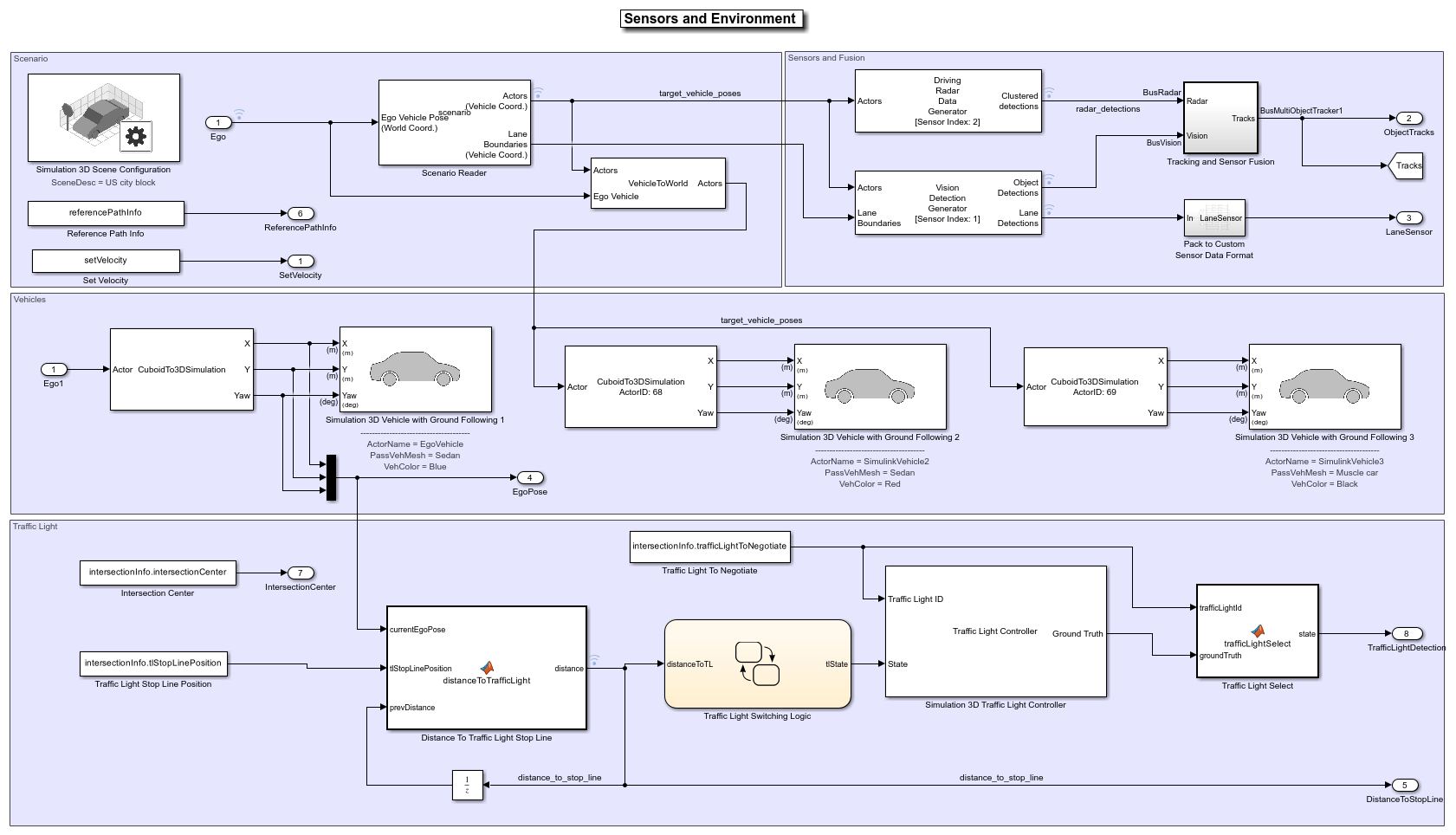
The Sensors and Environment subsystem configures the road network, sets vehicle positions, synthesizes sensors, and fuses the vehicle detections from the radar and vision sensors. Open the Sensors and Environment subsystem.
open_system("TLNWithUnrealTestBench/Sensors and Environment");
Select Scenario
The scene and road network required for the test bench model are specified by the following parts of this subsystem:
The scene name parameter
Scene nameof the Simulation 3D Scene Configuration block is set to US City Block. The US city block road network consists of fifteen one-way intersections with two traffic lights at each intersection. This example uses a section of the US city block scene to test the model.
The Scenario Reader block takes the ego vehicle information as input and performs a closed-loop simulation. This block reads the
drivingScenarioobjectscenariofrom the base workspace. The scenario contains the desired road network. The road network closely matches with a section of the US city block scene and contains one intersection.
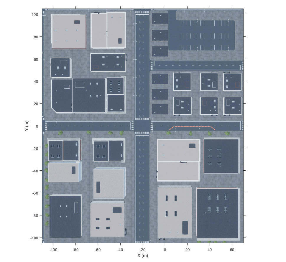
You can display the selected section of the US city block scene by using the helperDisplayTrafficLightScene function.
Specify the x and the y limits to select the desired scene area and plot the extracted scene.
xlimit = [-110 70];
ylimit = [-105 105];
hFigure = helperDisplayTrafficLightScene(xlimit, ylimit);
snapnow;
close(hFigure);
The helperGetTrafficLightScenario function specifies a reference path for the ego vehicle to follow when the lane information is not available. The Reference Path Info block reads the reference path stored in the base workspace variable referencePathInfo. The ego vehicle can either go straight or take a left turn at the intersection based on the reference trajectory. You can select one of these reference trajectories by setting the input values of helperGetTrafficLightScenario function. Set the value to
Straight- To make the ego vehicle travel straight through the intersection.
Left- To make the ego vehicle take a left turn at the intersection.
The Set Velocity block reads the velocity value from the base workspace variable setVelocity and gives as input to the controller.
Set Vehicle Positions
The scenario contains one ego vehicle and two non-ego vehicles. The positions for each vehicle in the scenario are specified by these parts of the subsystem:
The Simulation 3D Vehicle with Ground Following block provides an interface that changes the position and orientation of the vehicle in the 3D scene.
The Ego input port controls the position of the ego vehicle, which is specified by the
Simulation3DVehiclewithGroundFollowing1 block. TheActorNamemask parameter ofSimulation3DVehiclewithGroundFollowing1 block is specified asEgoVehicle.
The Cuboid To 3D Simulation block converts the ego pose coordinate system (with respect to below the center of the vehicle rear axle) to the 3D simulation coordinate system (with respect to below the vehicle center).
The Scenario Reader block also outputs ground truth information of lanes and actor poses in ego vehicle coordinates for the target vehicles. There are two target vehicles in this example, which are specified by the other Simulation 3D Vehicle with Ground Following blocks.
The Vehicle To World block converts the actor pose coordinates from ego vehicle coordinates to the world coordinates.
The Tracking and Sensor Fusion subsystem fuses vehicle detections from Driving Radar Data Generator and Vision Detection Generator blocks and tracks the fused detections using Multi-Object Tracker block to provide object tracks surrounding the ego vehicle. The Vision Detection Generator block also provides lane detections with respect to the ego vehicle that helps in identifying vehicles present in the ego lane.
Control Traffic Light in Unreal Scene
This model uses the Simulation 3D Traffic Light Controller helper block to configure and control the state of traffic lights in an Unreal scene. The Simulation 3D Traffic Light Controller helper block controls the state of traffic lights by using Timer-Based or State-Based mode. You can select the desired mode by using the Control mode mask parameter. By default, this model uses State-Based mode. For information on Timer-Based mode, see the block mask description.
In State-Based mode, the block overwrites the state of a traffic light specified by the Traffic Light ID input port. The value for the Traffic Light ID input port is set by the intersectionInfo.trafficLightToNegotiate variable in the helperGetTrafficLightScenario function. In this model, the value for Traffic Light ID input port is set to 16. This implies that the block controls the traffic light with ID value 16 in the US city block scene. The states of all the traffic lights present in the US city block scene is returned by the Ground Truth output port of the Simulation 3D Traffic Light Controller helper block. The model tests the decision logic and controls by using the ground truth information and does not require perception-based traffic light detection.
The Traffic Light Select block extracts the state of the traffic light with ID value 16 from the Ground Truth output. The Traffic Light Decision Logic reference model uses the state value to arbitrate between the lead car and the traffic light. For more information about the Traffic Light Decision Logic reference model, see the Traffic Light Negotiation example.
The Traffic Light Stop Line Position block provides the stop line position at the intersection corresponding to the selected traffic light trafficLightToNegotiate. The stop line position value is specified by intersectionInfo.tlStopLinePosition.
The Intersection Center block provides the position of the intersection center of the road network in the scenario. This is obtained using the intersectionInfo, an output from helperGetTrafficLightScenario.
It is often important to test the decision logic and controls when the ego vehicle is close to the traffic light and the traffic light changes its state. The model used in this example enables traffic lights to change state when the EgoVehicle is close to the traffic light.
The Distance To Traffic Light Stop Line block calculates the Euclidean distance between the stop line corresponding to the selected traffic light trafficLightToNegotiate and the current ego vehicle position.
The Traffic Light Decision Logic uses the distance value to decide the most important object (MIO), the closest object in front of the ego vehicle. It can be the lead vehicle or traffic light in the ego lane.
The Traffic Light Switching Logic block outputs tlState, the state of the traffic light that needs to be set. This is implemented using Stateflow® and uses the distance value to trigger a state change when the EgoVehicle is closer to the traffic light than the specified distance.
Open the Traffic Light Switching Logic block.
open_system("TLNWithUnrealTestBench/Sensors and Environment/" + ...
    "Traffic Light Switching Logic", 'force');
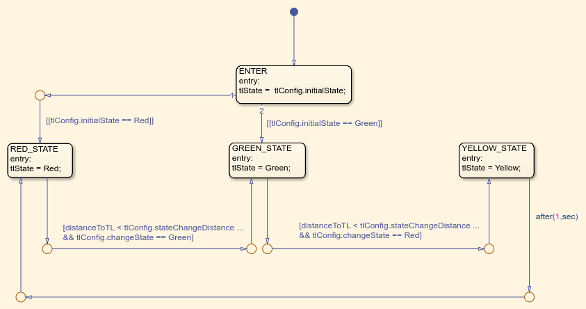
Traffic Light Switching Logic uses the Configuration params mask parameter to read the traffic light configuration, trafficLightConfig, from the base workspace. You can use the trafficLightConfig structure to configure different test scenarios. This structure is defined in the test scenario function and has the following fields: stateChangeDistance, initialState, and changeState.
initialStatespecifies the state of the traffic light before the state change.
stateChangeDistancespecifies the threshold distance of theEgoVehicleto the traffic light at which state change should happen.
changeStatespecifies the state of the traffic light to be set after state change.
State switching happens based on the set configuration and when EgoVehicle reaches stateChangeDistance. When the initialState is Red and changeState is Green the Stateflow chart switches from Red state to Green state. Conversely, when the initialState is Green and changeState is Red the Stateflow chart is modeled such that the state transition happens from Green state to Yellow state and after one second, the traffic light switches to Red state.
Simulate Vehicle Behavior During Green To Red Transition
This section tests the decision logic when the ego vehicle is at a close distance to the traffic light and the traffic light state changes from green to red. In this test scenario, a lead vehicle travels in the ego lane and crosses the intersection. The traffic light state keeps green for the lead vehicle and turns red when the ego vehicle is at a distance of 10 meters from the stop line. The ego vehicle is expected to follow the lead vehicle, negotiate the state transition, and come to a complete halt before the stop line.
Configure the TLNWithUnrealTestBench model to use the scenario_03_TLN_straight_greenToRed_with_lead_vehicle test scenario.
helperSLTrafficLightNegotiationWithUnrealSetup(...
    "scenario_03_TLN_straight_greenToRed_with_lead_vehicle");
Display the trafficLightConfig structure parameters set for the test scenario.
disp(trafficLightConfig');
           initialState: 2
    stateChangeDistance: 10
            changeState: 0
Simulate the model. During the simulation, the model logs the signals required for post simulation analysis to logsout.
To reduce command-window output, first turn off the MPC update messages.
mpcverbosity('off');
sim("TLNWithUnrealTestBench");
Plot the simulation results using helperPlotTrafficLightControlAndNegotiationResults function.
hFigResults = helperPlotTrafficLightControlAndNegotiationResults( ...
    logsout, trafficLightConfig.stateChangeDistance);
Examine the results.
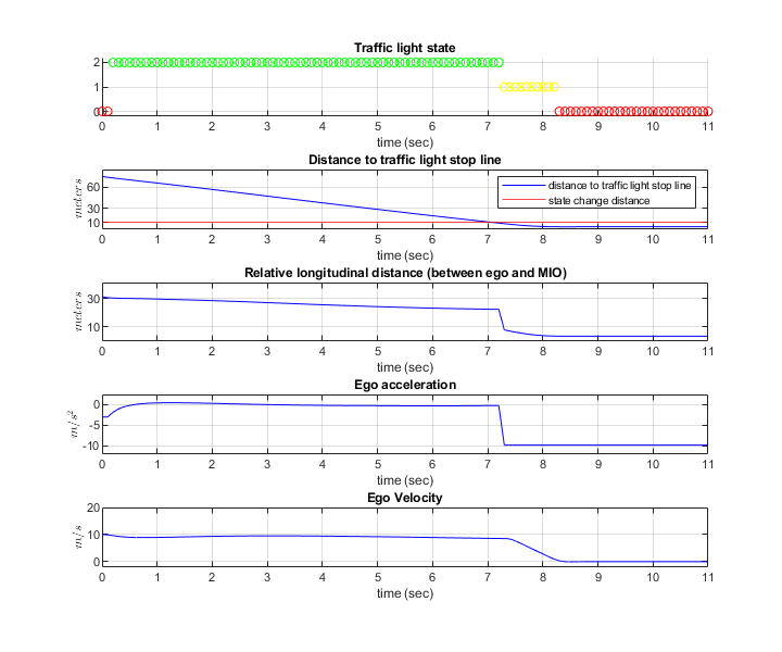
The Traffic light state plot shows the state of the traffic light. The Distance to traffic light stop line plot shows the distance between the ego vehicle and the stop line corresponding to the traffic light. You can see that the initial state of the traffic light is green and the state changes from green to yellow as the ego vehicle approaches the stop line. The state changes from yellow to red when the ego vehicle is at a distance of 10 meters from the stop line.
The Relative longitudinal distance plot shows the relative distance between the ego vehicle and the most important object (MIO). The MIO is the closest object in front of the ego vehicle. It can be a lead vehicle or a traffic light in the ego lane. The ego vehicle follows the lead vehicle and maintains a safe distance when the traffic light state is green. The distance between the ego and the lead vehicle decreases when the traffic light transitions from green to red. This is because, as the ego vehicle approaches the stop line, the traffic light is detected as an MIO. At this point of time, the traffic light state is either red or yellow.
The Ego acceleration plot shows the acceleration profile from the Lane Following Controller. Notice that this closely follows the dip in the relative distance, in reaction to the detection of the red traffic light as an MIO.
The Ego velocity plot shows the velocity profile of the ego vehicle. Notice that the ego velocity slows down in reaction to the yellow and red traffic lights and comes to a complete halt before the stop line. This can be verified by comparing the plot with Distance to traffic light stop line, when the velocity is zero.
You can refer to the Traffic Light Negotiation example to learn more about this analysis and the interactions between the decision logic and the controller.
Close the figure.
close(hFigResults);
Simulate Vehicle Behavior During Red To Green Transition
This section tests the decision logic when the ego vehicle is at a close distance to the traffic light and the traffic light state changes from red to green. In addition, a cross-traffic vehicle is in the intersection when the traffic light is green for the ego vehicle. The traffic light state is initially red for the ego vehicle and turns green when the ego vehicle is at a distance of 11 meters from the stop line. The ego vehicle is expected to slow down as it approaches the traffic light when the state is red and must start accelerating when the traffic light state changes from red to green. It is also expected to wait for the cross-traffic vehicle to pass the intersection before accelerating to continue its travel.
The test scenario function scenario_04_TLN_straight_redToGreen_with_cross_vehicle implements this scenario. Configure the TLNWithUnrealTestBench model to use this scenario.
helperSLTrafficLightNegotiationWithUnrealSetup(...
    "scenario_04_TLN_straight_redToGreen_with_cross_vehicle");
Display the trafficLightConfig structure parameters that are set for this test scenario.
disp(trafficLightConfig');
           initialState: 0
    stateChangeDistance: 11
            changeState: 2
Simulate the model.
sim("TLNWithUnrealTestBench");
Plot the simulation results.
hFigResults = helperPlotTrafficLightControlAndNegotiationResults( ...
    logsout, trafficLightConfig.stateChangeDistance);
Examine the results.
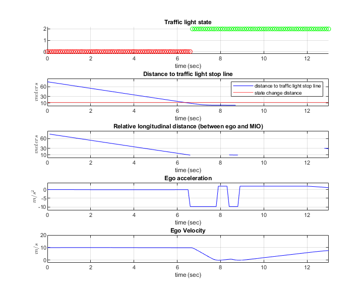
The Traffic light state plot shows that the initial traffic light state is red. The traffic light state changes from red to green when the ego vehicle is at a distance of 11 meters from the stop line.
The Relative longitudinal distance plot closely follows the Distance to traffic light stop line plot because there is no lead vehicle. Notice the sudden dip in the relative distance in response to the detection of the cross-over vehicle.
The Ego acceleration plot shows that the ego vehicle attempts to slow down on seeing the red traffic light. However, in response to the state change to green, you can observe an increase in acceleration. You can then notice a hard-braking profile in response to the cross-traffic vehicle at the intersection.
The Ego velocity plot closely follows the Ego acceleration plot and shows a decrease in velocity as the ego vehicle approaches the intersection. You can also notice a slight increase in velocity in response to green traffic light and subsequent decrease in velocity in response to the cross-traffic vehicle.
Close the figure.
close(hFigResults);
Explore Other Scenarios
In the previous sections, you explored the system behavior for the scenario_03_TLN_straight_greenToRed_with_lead_vehicle and scenario_04_TLN_straight_redToGreen_with_cross_vehicle scenarios. Below is a list of scenarios that are compatible with TLNWithUnrealTestBench.
scenario_01_TLN_left_redToGreen_with_lead_vehicle
scenario_02_TLN_straight_greenToRed
scenario_03_TLN_straight_greenToRed_with_lead_vehicle [Default]
scenario_04_TLN_straight_redToGreen_with_cross_vehicle
Use these additional scenarios to analyze TLNWithUnrealTestBench under different conditions.
Enable the MPC update messages.
mpcverbosity('on');
You can use the modeling patterns in this example to build your own traffic light negotiation application.
See Also
Simulation 3D Scene Configuration | Simulation 3D Vehicle with Ground Following | Vehicle To World | Cuboid To 3D Simulation | Driving Radar Data Generator | Vision Detection Generator | Multi-Object Tracker