allpass2wdf
Allpass to Wave Digital Filter coefficient transformation
Description
W = allpass2wdf(A)A.
Each cell of A holds the coefficients of a section
of a cascade allpass filter. W is also a cell
array, and each cell of W contains the transformed
version of the coefficients in the corresponding cell of A.
W can be used with allpass filter objects such as dsp.AllpassFilter and dsp.CoupledAllpassFilter,
with structure set to 'Wave Digital Filter'.
Examples
Create a second order allpass filter with coefficients a = [0 0.5]. Convert these coefficients into wave digital filter form using allpass2wdf. Assign the transformed coefficients to an allpass filter using the wave digital filter structure. Pass a random input to both these filters and compare the outputs.
a = [0 0.5];
allpass = dsp.AllpassFilter('AllpassCoefficients', a);
w = allpass2wdf(a);
allpasswdf = dsp.AllpassFilter('Structure', 'Wave Digital Filter',...
    'WDFCoefficients', w);
in = randn(512, 1);
outputAllpass = allpass(in);
outputAllpasswdf = allpasswdf(in);
plot(outputAllpass-outputAllpasswdf)
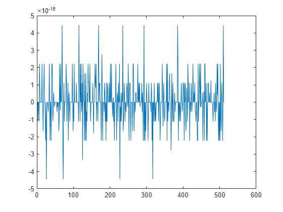
The difference between the two outputs is very small.
Input Arguments
Output Arguments
Algorithms
In the more general case, the input coefficients A define
a cascade or multisection allpass filter. allpass2wdf applies
separately to each section of the same transformation used in the
single-section case. In the single-section case, the numeric coefficients
vector a contains a standard polynomial representation
of an allpass filter of order 1, 2, or 4. For example, in the first
order case,
represents the first order transfer function:
and in the second order case,
represents the second order transfer function:
.
The allpass transfer functions H1 and H2 can also have the following alternative representations, using decoupled coefficients in vector w1 or w2 respectively.
For allpass coefficients, w is often used
to derive adaptor multipliers for Wave Digital Filter structures,
and it is required by a number of allpass based filters in DSP System Toolbox™ when Structure is
set to 'Wave Digital Filter' (e.g. dsp.AllpassFilter,
and dsp.CoupledAllpassFilter).
For a given vector of section coefficients a, allpass2wdf computes
the corresponding vector w such that
This results in using the following formulas:
References
[1] M. Lutovac, D. Tosic, B. Evans, Filter Design for Signal Processing using MATLAB and Mathematica. Prentice Hall, 2001.
Version History
Introduced in R2014a