Main Content

dsp.CoupledAllpassFilter

Coupled allpass IIR filter

Description

The dsp.CoupledAllpassFilter object implements a coupled allpass filter structure composed of two allpass filters connected in parallel. Each allpass branch can contain multiple sections. The overall filter output is computed by adding the output of the two respective branches. An optional second output can also be returned, which is power complementary to the first. For example, from the frequency domain perspective, if the first output implements a lowpass filter, the second output implements the power complementary highpass filter. For real signals, the power complementary output is computed by subtracting the output of the second branch from the first. dsp.CoupledAllpassFilter supports double- and single-precision floating point and allows you to choose between different realization structures. This System object™ also supports complex coefficients, multichannel variable length input, and tunable filter coefficient values.

To filter each channel of the input:

  1. Create the dsp.CoupledAllpassFilter object and set its properties.

  2. Call the object with arguments, as if it were a function.

To learn more about how System objects work, see What Are System Objects?

Creation

Description

caf = dsp.CoupledAllpassFilter returns a coupled allpass filter System object, caf, that filters each channel of the input signal independently. The coupled allpass filter uses the default inner structures and coefficients.

caf = dsp.CoupledAllpassFilter(AllpassCoeffs1,AllpassCoeffs2) returns a coupled allpass filter System object, caf, with Structure set to 'Minimum multiplier', AllpassCoefficients1 set to AllpassCoeffs1, and AllpassCoefficients2 set to AllpassCoeffs2.

example

caf = dsp.CoupledAllpassFilter(struc,AllpassCoeffs1,AllpassCoeffs2) returns a coupled allpass filter System object, caf, with Structure set to struc and the relevant coefficients set to AllpassCoeffs1 and AllpassCoeffs2. struc can be 'Minimum multiplier' | 'Wave Digital Filter' | 'Lattice'.

caf = dsp.CoupledAllpassFilter(Name,Value) returns a Coupled allpass filter System object, caf, with each property set to the specified value.

Properties

expand all

Unless otherwise indicated, properties are nontunable, which means you cannot change their values after calling the object. Objects lock when you call them, and the release function unlocks them.

If a property is tunable, you can change its value at any time.

For more information on changing property values, see System Design in MATLAB Using System Objects.

Specify the internal structure of allpass branches as one of 'Minimum multiplier', 'Wave Digital Filter', or 'Lattice'. Each structure uses a different pair of coefficient values, independently stored in the relevant object property.

Specify the polynomial filter coefficients for the first allpass branch. This property can accept values either in the form of a row vector (single-section configuration) or a cell array with as many cells as filter sections.

Tunable: Yes

Dependencies

This property is applicable only if you set the Structure property to 'Minimum multiplier'.

Data Types: single | double

Specify the Wave Digital Filter coefficients for the first allpass branch. This property can accept values either in the form of a row vector (single-section configuration) or a cell array with as many cells as filter sections.

Tunable: Yes

Dependencies

This property is applicable only if you set the Structure property to 'Wave Digital Filter'.

Data Types: single | double

Specify the allpass lattice coefficients for the first allpass branch. This property can accept values either in the form of a row vector (single-section configuration) or a cell array with as many cells as filter sections.

Tunable: Yes

Dependencies

This property is applicable only if you set the Structure property to 'Lattice'.

Data Types: single | double

Integer number of the delay taps in the top branch, specified as a positive integer scalar.

Tunable: Yes

Dependencies

This property is applicable only if you set the PureDelayBranch property to true.

Data Types: single | double | int8 | int16 | int32 | int64 | uint8 | uint16 | uint32 | uint64

Gain1 is the individual branch phase gain. This property can accept only values equal to '1', '–1', '0+i', or '0–i'. This property is nontunable.

Data Types: char

Specify the polynomial filter coefficients for the second allpass branch. This property can accept values either in the form of a row vector (single-section configuration) or a cell array with as many cells as filter sections.

Tunable: Yes

Dependencies

This property is applicable only if you set the Structure property to 'Minimum multiplier'.

Data Types: single | double

Specify the Wave Digital Filter coefficients for the second allpass branch. This property can accept values either in the form of a row vector (single-section configuration) or a cell array with as many cells as filter sections.

Tunable: Yes

Dependencies

This property is applicable only if you set the Structure property to 'Wave Digital Filter'.

Data Types: single | double

Specify the allpass lattice coefficients for the second allpass branch. This property can accept values either in the form of a row vector (single-section configuration) or a cell array with as many cells as filter sections.

Tunable: Yes

Dependencies

This property is applicable only if you set the Structure property to 'Lattice'.

Data Types: single | double

Specify the value of the independent phase gain applied to branch 2. This property can accept only values equal to '1', '–1', '0+i', or '0–i'. This property is nontunable.

Data Types: char

Specify the value of the phasor gain in complex conjugate form, in each of the two branches, and in complex coefficient configuration. The absolute value of this property should be 1 and its default value is 1.

Tunable: Yes

Dependencies

This property is applicable only when the selected Structure property supports complex coefficients.

Data Types: single | double

If you set PureDelayBranch to true, the property holding the coefficients for the first allpass branch is disabled and Delay becomes enabled. You can use this property to improve performance, when one of the two allpass branches is known to be a pure delay (e.g. for halfband filter designs)

Data Types: logical

When the input signal is real, this property triggers the use of an optimized structural realization. This property enables providing complex coefficients for only the first branch. The coefficients for the second branch are automatically inferred as complex conjugate values of the first branch coefficients

Dependencies

This property is only enabled if the currently selected structure supports complex coefficients. Use it only if the filter coefficients are actually complex.

Data Types: logical

Usage

Description

y = caf(x) filters the input signal x to produce the output y. When x is a matrix, each column is filtered independently as a separate channel over time.

example

[y,ypc] = caf(x) also returns ypc, the power complementary signal to the primary output y.

Input Arguments

expand all

Data input, specified as a vector or a matrix. This object also accepts variable-size inputs. Once the object is locked, you can change the size of each input channel, but you cannot change the number of channels.

Data Types: single | double
Complex Number Support: Yes

Output Arguments

expand all

Lowpass filtered output, returned as a vector or a matrix. The size and data type of the output signal matches that of the input signal.

Data Types: double | single
Complex Number Support: Yes

Power complimentary highpass filtered output, returned as a vector or a matrix. The size and data type of the output signal matches that of the input signal.

Data Types: double | single
Complex Number Support: Yes

Object Functions

To use an object function, specify the System object as the first input argument. For example, to release system resources of a System object named obj, use this syntax:

release(obj)

expand all

getBranchesReturn internal allpass branches
freqzFrequency response of discrete-time filter System object
impzImpulse response of discrete-time filter System object
infoInformation about filter System object
coeffsReturns the filter System object coefficients in a structure
costEstimate cost of implementing filter System object
grpdelayGroup delay response of discrete-time filter System object
stepRun System object algorithm
releaseRelease resources and allow changes to System object property values and input characteristics
resetReset internal states of System object

Examples

collapse all

Realize a Butterworth lowpass filter of order 3. Use a coupled allpass structure with inner minimum multiplier structure.

Fs = 48000;    % in Hz
Fc = 12000;    % in Hz
frameLength = 1024;
[b, a] = butter(3,2*Fc/Fs);
AExp = [freqz(b,a,frameLength/2); NaN];
[c1, c2] = tf2ca(b,a);
caf = dsp.CoupledAllpassFilter(c1(2:end),c2(2:end));
tfe = dsp.TransferFunctionEstimator('FrequencyRange', 'onesided',...
    'SpectralAverages', 2);
aplot = dsp.ArrayPlot('PlotType', 'Line',...
    'YLimits', [-40 5],...
    'YLabel', 'Magnitude (dB)',...
    'SampleIncrement', Fs/frameLength,...
    'XLabel', 'Frequency (Hz)',...
    'Title', 'Magnitude Response',...
    'ShowLegend', true,'ChannelNames',{'Actual','Expected'});
Niter = 200;
for k = 1:Niter
    in = randn(frameLength,1);
    out = caf(in);
    A = tfe(in,out);
    aplot(db([A,AExp]));
end

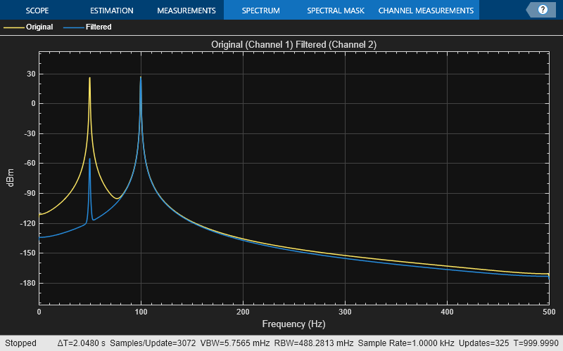
Remove a low-frequency sinusoid using an elliptic highpass filter design implemented through a coupled allpass structure.

Initialize

Fs = 1000;
f1 = 50; f2 = 100;
Fpass = 70; Apass = 1;
Fstop = 60; Astop = 80;
filtSpecs = fdesign.highpass(Fstop,Fpass,Astop,Apass,Fs);
hpSpec = design(filtSpecs,'ellip','FilterStructure','cascadeallpass',...
    'SystemObject',true);
frameLength = 1000;
nFrames = 100;
sine   = dsp.SineWave('Frequency',[f1,f2],'SampleRate',Fs,...
  'SamplesPerFrame',frameLength); % Input composed of two sinusoids.

sa = spectrumAnalyzer('SampleRate',Fs,...
  'PlotAsTwoSidedSpectrum',false,'ShowLegend',true,...
  'Method','welch','AveragingMethod','exponential',...
  'Title','Original (Channel 1) Filtered (Channel 2)',...
  'ChannelNames',{'Original','Filtered'});

Simulate

for k = 1:1000
  original = sum(sine(),2); % Add the two sinusoids together
  filtered = hpSpec(original);
  sa([original,filtered]);
end
release(sa)

Design a Butterworth lowpass filter of order 3. Use a coupled allpass structure with inner minimum multiplier structure.

Fs = 48000;    % in Hz
Fc = 12000;    % in Hz
frameLength = 1024;
[b,a] = butter(3,2*Fc/Fs);
AExp = [freqz(b,a,frameLength/2); NaN];
[c1,c2] = tf2ca(b,a);
caf = dsp.CoupledAllpassFilter(c1(2:end),c2(2:end));

Using the 'SubbandView' option of the dsp.CoupledAllpassFilter, you can visualize the lowpass filter output, the power complementary highpass filter output, or both using the fvtool.

To view the lowpass filter output, set 'SubbandView' to 1.

fvtool(caf,'SubbandView',1,'Fs',Fs)

To view the highpass filter output, set 'SubbandView' to 2.

fvtool(caf,'SubbandView',2,'Fs',Fs)

To view both the outputs, set 'SubbandView' to 'all', [1 2] or [1;2].

fvtool(caf,'SubbandView','all','Fs',Fs);

Algorithms

The following three figures summarize the main structures supported by dsp.CoupledAllpassFilter.

  • Minimum Multiplier and WDF

  • Lattice

  • Lattice with Complex Conjugate Coefficients

References

[1] Regalia, Philip A., Mitra, Sanjit K., and P.P Vaidyanathan “ The Digital All-Pass Filter: A Versatile Signal Processing Building Block.” Proceedings of the IEEE 1988, Vol. 76, No. 1, pp. 19–37.

[2] Mitra, Sanjit K., and James F. Kaiser, "Handbook for Digital Signal Processing" New York: John Wiley & Sons, 1993.

Version History

Introduced in R2013b