Digital Down-Converter
Translate digital signal from intermediate frequency (IF) band to baseband and decimate it
Libraries:
DSP System Toolbox /
Signal Operations
Description
The Digital Down-Converter (DDC) block converts a digitized real signal centered at an intermediate frequency (IF) to a baseband complex signal centered at zero frequency. The DDC block downsamples the frequency downconverted signal using a cascade of three decimation filters. This block designs the decimation filters according to the filter parameters you set in the block dialog box.
Examples
Digital Up and Down Conversion for Family Radio Service in Simulink
Implement Family Radio Service system using Digital Down-Converter and Digital Up-Converter blocks.
Ports
Input
Output
Parameters
Main Tab
Specify the decimation factor as a positive integer ≥ 2, or as a 1-by-2 or 1-by-3 vector of positive integers.
When you set this parameter to a scalar value, the block applies the same decimation factor to the three decimation filtering stages.
When you set this parameter to a 1-by-2 vector, the block applies the first and second values in the vector to the first and second filtering stages, respectively, and bypasses the third stage. Both elements of Decimation factor must be greater than 1.
When you set this parameter to a 1-by-3 vector, the block applies the values in the vector to the corresponding filtering stages. The first and second elements of Decimation factor must be greater than 1, and the third element must be 1 or 2.
When you select this check box, the block designs filters with the minimum possible order that meets the requirements specified in these parameters:
Passband ripple of cascade response (dB)
Stopband attenuation of cascade response (dB)
Two-sided bandwidth of input signal
Source of stopband frequency
Stopband frequency
When you clear this check box, the block designs filters with orders that you specify in Number of sections of CIC decimator, Order of CIC compensation filter stage, and Order of third filter stage. The filter designs meet the passband and stopband frequency specifications that you set in Two-sided bandwidth of input signal, Source of stopband frequency, and Stopband frequency. By default, this check box is selected.
Specify the number of sections in the CIC decimator as a positive integer.
Dependencies
To enable this parameter, clear the Minimum order filter design parameter.
Specify the order of the third filter stage as an even positive integer. When you specify Decimation factor as a 1-by-2 vector, the block ignores the value in this parameter because the block bypasses the third filter stage.
Dependencies
To enable this parameter, clear the Minimum order filter design parameter.
Specify the source of the stopband frequency as
Auto or
Property.
When you set this parameter to Auto and set:
Sample rate mode to
Specify on dialog— The block places the cutoff frequency of the cascade filter response at approximately Fc = SampleRate/(2M) Hz, where M is the total decimation factor specified in Decimation factor. SampleRate is the input sample rate that you specify in the Input sample rate (Hz) parameter. The block computes the stopband frequency as Fstop = Fc + (TW/2). TW is the transition bandwidth of the cascade response, computed as 2×(Fc–Fp), where the passband frequency Fp equals Bandwidth/2.Sample rate mode to
Inherit from input port— The block places the cutoff frequency of the cascade filter response at approximately Fc = SampleRate/(2M) Hz, where M is the total decimation factor specified in Decimation factor. SampleRate is computed as1/ Ts, where Ts is the sample time of the input signal. The block computes the stopband frequency as Fstop = Fc + (TW/2). TW is the transition bandwidth of the cascade response, computed as 2×(Fc–Fp), where the passband frequency Fp equals Bandwidth/2.Sample rate mode to
Use
											normalized frequency (0 to 1)
— The block places the cutoff frequency of the cascade filter response at approximately Fc = 1/M , where M is the total decimation factor that you specify in Decimation factor. The block computes the stopband frequency as Fstop = Fc + (TW/2). TW is the transition bandwidth of the cascade response computed as 2×(Fc–Fp), and the passband frequency Fp equals Bandwidth/2.
When you set this parameter to Property, specify the stopband
frequency in Stopband frequency.
Specify the oscillator type as one of the following:
Sine wave— The block performs frequency down conversion on the input signal using a complex exponential obtained from samples of a sinusoidal trigonometric function.NCO— The block performs frequency down conversion on the input signal with a complex exponential obtained using a numerically controlled oscillator (NCO).Input port— The block performs frequency down conversion on the input signal using the complex signal that you provide through the Osc input port.None— The block does not require the mixer stage and acts as a three-stage cascaded decimator.
Specify the center frequency of the output signal as a positive scalar in Hz or in normalized frequency units (since R2024b).
If you set the Sample rate mode parameter to:
Specify on dialogorInherit from input port— The value of the center frequency is in Hz and must be less than half the sample rate of the input signal. The block downconverts the input signal from the passband center frequency, which you specify in Center frequency of output signal, to0Hz.Use normalized frequency (0 to 1)— The value of the center frequency is in normalized frequency units. The value must be a positive scalar less than or equal to1.0.
(since R2024b)
Dependency
To enable this parameter, set Type of
oscillator to Sine wave or
NCO.
Specify the order of the CIC compensation filter stage as a positive integer.
Dependencies
To enable this parameter, clear the Minimum order filter design parameter.
Specify the two-sided bandwidth of the input signal as a positive scalar in Hz or in normalized frequency units (since R2024b). The
block sets the passband frequency of the cascade of filters to half of
the value you specify in this parameter. Set the value of this parameter
to less than Input sample rate
(Hz)/Decimation factor. When you set
Sample rate mode to Inherit from
input port, set this value to less than
((1/Ts)/Decimation
factor), where Ts is the sample time
of the input signal. If you set Sample rate mode to
Use normalized frequency (0 to 1), set
this value to less than 1/Decimation factor.
Specify the stopband frequency as a positive scalar in Hz or in normalized frequency units (since R2024b).
Dependencies
To enable this parameter, set Source of stopband
frequency to
Property.
Specify the passband ripple of the cascade response in dB as a double-precision positive scalar. When you select the Minimum order filter design, the block designs the filters so that the cascade response meets the passband ripple that you specify in Passband ripple of cascade response (dB).
Dependencies
To enable this parameter, select the Minimum order filter design parameter.
Specify the stopband attenuation of the cascade response in dB as a double-precision positive scalar. When you select the Minimum order filter design parameter, the block designs the filters such that the cascade response meets the stopband attenuation that you specify in this parameter.
Dependencies
To enable this parameter, select the Minimum order filter design parameter.
Specify the number of NCO accumulator bits as an integer scalar in the
range [1 128].
Dependencies
To enable this parameter, set Type of
oscillator to NCO.
Specify the number of NCO quantized accumulator bits as an integer
scalar in the range [1 128]. This value must be less
than the value you specify in Number of NCO accumulator
bits.
Dependencies
To enable this parameter, set Type of
oscillator to NCO.
When you select this check box, the block applies dither to the NCO signal according to the number of dither bits you specify in Number of NCO dither bits. By default, this check box is selected.
Dependencies
To enable this parameter, set Type of
oscillator to NCO.
Specify the number of NCO dither bits as an integer scalar smaller than the number of accumulator bits in Number of NCO accumulator bits.
Dependencies
To enable this parameter, set Type of
oscillator to NCO and
select the Dither control for NCO
parameter.
Since R2024b
Specify the input sample rate using one of these options:
Use normalized frequency (0 to
											1)
— Specify the center frequency, two-sided bandwidth, and stopband frequency in normalized frequency units (0 to 1).Specify on dialog— Specify the input sample rate in the block dialog box using the Input sample rate (Hz) parameter.Inherit from input port— The block inherits the sample rate from the input signal. The block computes the sample rate asN/Ts, where N is the frame size of the input signal, and Ts is the sample time of the input signal.
Specify the sample rate of the input signal in Hz as a positive scalar greater than or equal to twice the value in Center frequency of output signal.
Dependencies
To enable this parameter,
set the Sample rate mode parameter to
Specify on dialog. (since R2024b)
Click this button to open the Filter Visualization Tool (FVTool) and display the magnitude and phase response of each stage as well as the cascade of stages in the Digital Down-Converter. The response is based on the values you specify in the block parameters dialog box. Changes made to these parameters update FVTool.
To update the magnitude response while FVTool is running, modify the parameters in the dialog box and click Apply.
Specify the type of simulation to run. You can set this parameter to:
Interpreted execution— Simulate model using the MATLAB® interpreter. This option shortens startup time.Code generation— Simulate model using generated C code. The first time you run a simulation, Simulink® generates C code for the block. The C code is reused for subsequent simulations as long as the model does not change. This option requires additional startup time but provides faster subsequent simulations.
Data Types Tab
Specify the data type of the input in the first, second, and third filter stages. You can set this parameter to one of the following:
Inherit: Same as
							input
(default) — The block inherits the Stage input data type from the input signal.fixdt([],16,0)— The block uses the fixed-point data type with binary-point scaling. Specify the sign mode of this data type as[]ortrue.An expression that evaluates to a data type, for example,
numerictype([],16,15). Specify the sign mode of this data type as[]ortrue.
For help with setting the stage input parameter, you can click the
Show data type assistant button
![]() to display the data type
assistant.
to display the data type
assistant.
See Specify Data Types Using Data Type Assistant (Simulink) for more information.
Specify the data type of the block output. You can set this parameter to:
Inherit: Same as input(default) — The block Inherits the output datatype from the input.fixdt([],16,0)— The block uses the fixed-point data type with binary point scaling. Specify the sign mode of this data type as[]ortrue.An expression that evaluates to a data type, for example,
numerictype([],16,15). Specify the sign mode of this data type as[]ortrue.
For help with setting the Output parameter, you
can click the Show data type assistant button
![]() to display the data type
assistant.
to display the data type
assistant.
See Specify Data Types Using Data Type Assistant (Simulink) for more information.
Specify the minimum value of the block output. The default value is
[] (unspecified). Simulink software uses this value to perform:
Simulation range checking (see Specify Signal Ranges (Simulink))
Automatic scaling of fixed-point data types
Maximum value of the block output. The default value is
[] (unspecified). Simulink software uses this value to perform:
Simulation range checking (see Specify Signal Ranges (Simulink))
Automatic scaling of fixed-point data types
Block Characteristics
Data Types |
|
Direct Feedthrough |
|
Multidimensional Signals |
|
Variable-Size Signals |
|
Zero-Crossing Detection |
|
More About
The following block diagram represents the DDC arithmetic with signed fixed-point inputs.
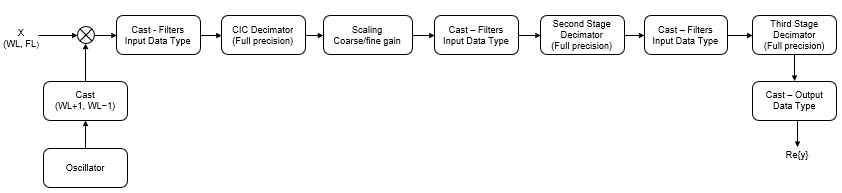
WLis the word length of the input, andFLis the fraction length of the input.The input of each filter is cast to the filter input data type. In the
dsp.DigitalDownConverterobject, you can specify the filter input data type through theFiltersInputDataTypeandCustomFiltersInputDataTypeproperties. In the Digital Down-Converter block, you can specify the filter input data type through the Stage input parameter.The oscillator output is cast to a word length equal to the input word length plus one. The fraction length is equal to the input word length minus one.
The scaling at the output of the CIC decimator consists of coarse- and fine-gain adjustments. The coarse gain is achieved using the
reinterpretcast(Fixed-Point Designer) function on the CIC decimator output. The fine gain is achieved using full-precision multiplication.
The following figure depicts the coarse-gain and fine-gain operations.
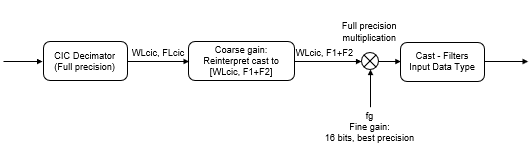
If the normalization gain is G (where 0<G≦1), then:
WLcicis the word length of the CIC decimator output andFLcicis the fraction length of the CIC decimator output.F1 = abs(nextpow2(G)), indicating the part of G achieved using bit shifts (coarse gain).F2= fraction length specified by the filter input data type.fg = fi((2^F1)*G, true, 16), which indicates that the remaining gain cannot be achieved with a bit shift (fine gain).
Algorithms
The digital downconverter downconverts the input signal by multiplying it with a complex exponential that has the specified center frequency. The algorithm downsamples the frequency downconverted signal using a cascade of three decimation filters. In this case, the filter cascade consists of a CIC decimator, a CIC compensator, and a third FIR decimation stage. The following block diagram shows the architecture of the digital downconverter.
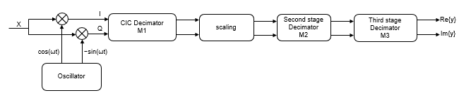
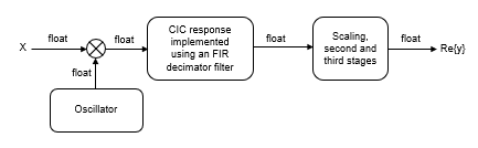
The scaling section normalizes the CIC gain and the oscillator power. It can also contain a correction factor to achieve the desired ripple specification. When you specify an oscillator signal through the input port, the normalization factor does not include the oscillator power factor. Depending on how you set the decimation factor, the block bypasses the third filter stage. When the input data type is double or single, the algorithm implements an N-section CIC decimation filter as an FIR filter with a response that corresponds to a cascade of N boxcar filters. The algorithm emulates a CIC filter with an FIR filter so that you can run simulations with floating-point data. When the input data type is fixed-point, the algorithm implements a true CIC filter with actual comb and integrator sections.
This block diagram represents the DDC arithmetic with single or double-precision, floating-point inputs.
For details about fixed-point operation, see Fixed Point.