IIR Halfband Decimator
Decimate signal using polyphase IIR halfband filter
Libraries:
DSP System Toolbox /
Filtering /
Multirate Filters
Description
The IIR Halfband Decimator block performs polyphase decimation of the input signal by a factor of 2. To design the halfband filter, you can specify the block to use an elliptic design or a quasi-linear phase design. The block uses these design methods to compute the filter coefficients. To filter the inputs, the block uses a polyphase structure. The allpass filters in the polyphase structure are in a minimum multiplier form.
Elliptic design introduces nonlinear phase and creates the filter using fewer coefficients than the quasi-linear design. Quasi-linear phase design overcomes phase nonlinearity at the cost of additional coefficients.
Alternatively, instead of designing the halfband filter using a design method, you can specify the filter coefficients directly. When you choose this option, the allpass filters in the two branches of the polyphase implementation can be in a minimum multiplier form or a wave digital form.
You can also use the block to implement the analysis portion of a two-band filter bank to filter a signal into lowpass and highpass subbands. For more details, see Algorithms.
Examples
Since R2023b
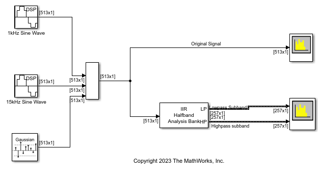
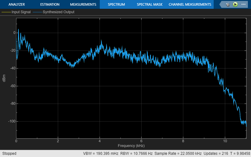
Design and implement an IIR halfband decimator using the IIR Halfband Decimator block. Pass a noisy input through the decimator. Plot the spectrum of the input and the decimated subband outputs in the spectrum analyzer.
This example also shows how to use the Allow arbitrary frame length for fixed-size input signals parameter.
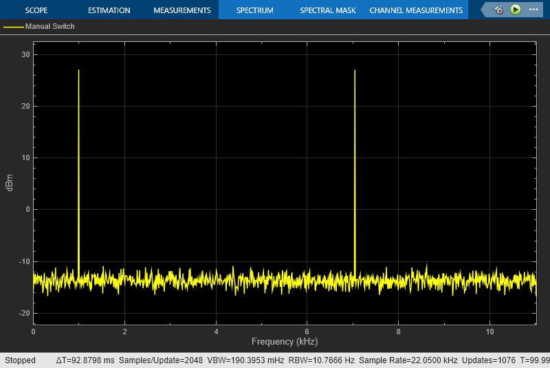
Open and inspect the DesignAndImplementIIRHalfbandDecimator model. The input signal in the model is a noisy sinusoidal signal with 513 samples per frame and contains two frequencies, one at 1 kHz and the other at 15 kHz. The Random Source block adds white Gaussian noise with a mean of 0 and a variance of 0.05 to this signal. The input signal is a fixed-size signal, that is, the frame length of the signal (513 samples per frame) does not vary during simulation.
To allow an arbitrary frame length for a fixed-size signal, that is, to allow a frame length that is not a multiple of the decimation factor 2, select the Allow arbitrary frame length for fixed-size input signals parameter in the IIR Halfband Decimator block dialog box.
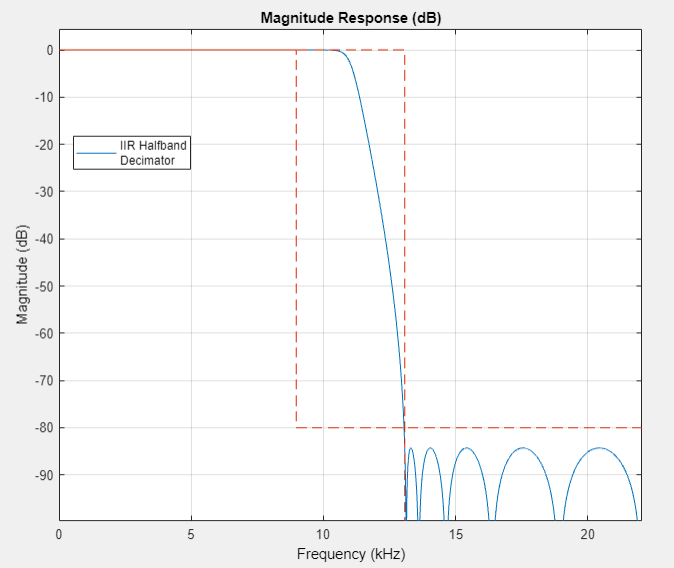
The IIR halfband decimator has a transition width of 4.1 kHz and a stopband attenuation of 80 dB. The decimator outputs the highpass subband signal.
Visualize the magnitude response of the filter by clicking the View Filter Response button in the block dialog box.
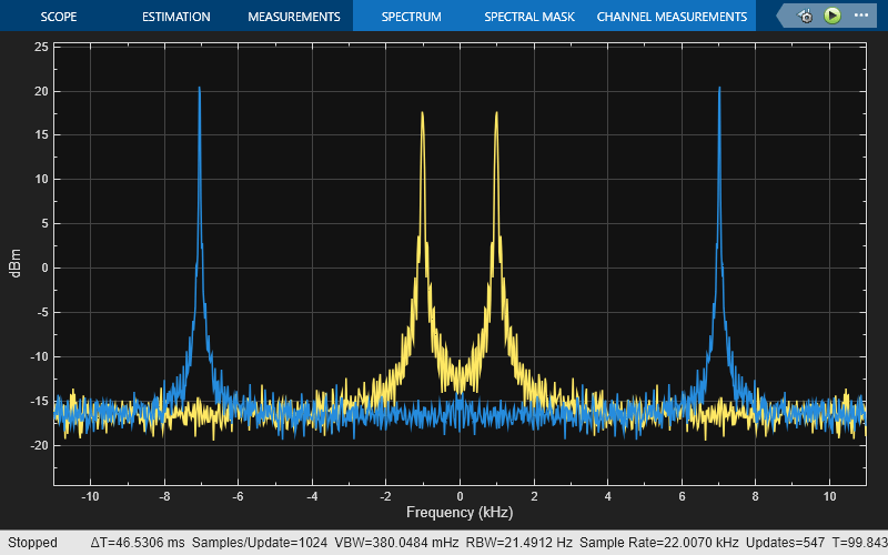
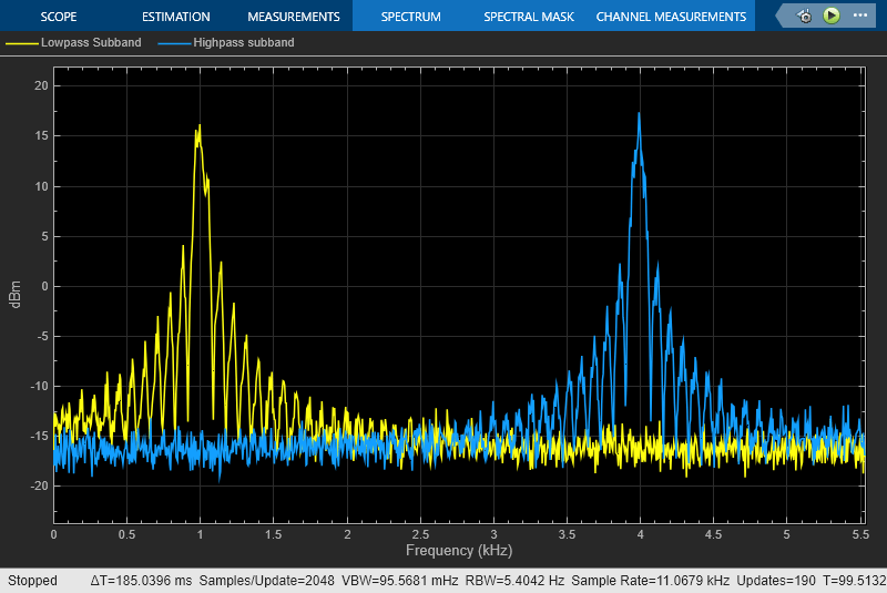
Pass the noisy sinusoidal signal through the decimator. Plot the spectrum of the input and the lowpass and highpass subband outputs in two separate spectrum analyzer windows.

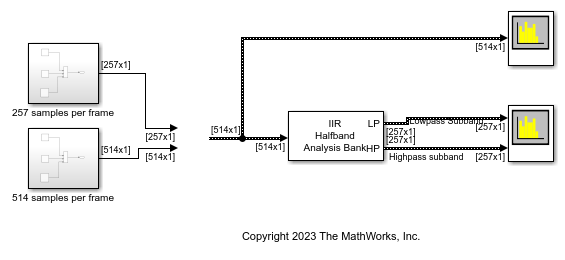
The block allows arbitrary frame lengths for variable-size signals irrespective of the setting of the Allow arbitrary frame length for fixed-size input signals parameter. When the input is a variable-size signal, the frame length of the signal can vary during simulation.
Open the DesignAndImplementIIRHalfbandDecimator_Varsize model. The input is a variable-size signal. The input frame length can vary between 257 and 514 samples per frame.
Since R2023b
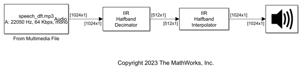
Use the IIR Halfband Decimator and IIR Halfband Interpolator blocks to extract and reconstruct the low-frequency subband from a speech signal.
Open and inspect the ExtractLowFrequencySubbandFromSpeechIIR.slx model. The input audio data is a single-channel speech signal with the sample rate of 22050 Hz.
Specify the Sample rate mode parameter of the IIR Halfband Decimator and IIR Halfband Interpolator blocks to Use normalized frequency (0 to 1). This option enables you to specify the transition width of the decimation and interpolation filters in normalized frequency units. Set the transition width to 0.093 in normalized frequency units and the stopband attenuation to 80 dB. The design method is Elliptic by default.
Read the speech signal from the audio file in frames of 1024 samples. The IIR Halfband Decimator block extracts and outputs the lowpass subband of the speech signal. The IIR Halfband Interpolator block reconstructs the lowpass approximation of the speech signal by interpolating the lowpass subband.
The Audio Device Writer block plays the filtered output.
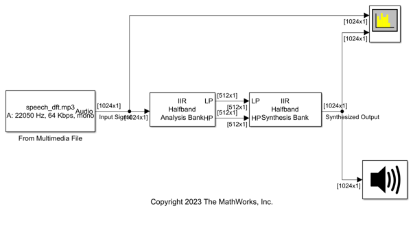
Use the IIR Halfband Decimator and IIR Halfband Interpolator blocks to implement a two-channel filter bank. This example uses an audio file input and shows that the power spectrum of the filter bank output does not differ significantly from the input. Play the output of the filter bank using the Audio Device Writer block.
Open and inspect the TwoChannelIIRFilterBank model. The input audio data is a single-channel speech signal with a sample rate of 22050 Hz.
The IIR Halfband Decimator block acts as an IIR halfband analysis bank as the Output highpass subband parameter is selected in the block dialog box. The IIR Halfband Interpolator block acts as an IIR halfband synthesis bank as the Input highpass subband parameter is selected in the block dialog box.
Set the Sample rate mode parameter in the IIR Halfband Decimator and IIR Halfband Interpolator blocks to Inherit from input port so that the blocks inherit the sample rate from the respective input ports. Set the transition width to 4.1 kHz and the stopband attenuation to 80 dB. The design method is set to Elliptic by default.
Read the speech signal from the audio file in frames of 1024 samples. The IIR halfband analysis filter bank extracts the lowpass and highpass subbands of the speech signal. The IIR halfband synthesis filter bank synthesizes the speech signal from the lowpass and highpass subbands.
Display the power spectrum of the audio input and the output from the synthesis filter bank in the spectrum analyzer. Play the synthesized speech signal using the Audio Device Writer block.
Ports
Input
Output
Parameters
Select the parameters that the block uses to design the IIR halfband filter. Because the filter design has only two degrees of freedom, you can specify only two of the three parameters:
Transition width and stopband
										attenuation
(default) — Design the filter using Transition width (Hz) and Stopband attenuation (dB). This design is the minimum order design.Filter order and transition width— Design the filter using Filter order and Transition width (Hz).Filter order and stopband attenuation— Design the filter using Filter order and Stopband attenuation (dB).Coefficients— Specify the filter coefficients directly using the enabled parameters.
Specify the transition width of the IIR halfband filter as a real positive scalar in Hz or in normalized frequency units (since R2023b).
If you set the Sample rate mode parameter to:
Specify on dialogorInherit from input port— The value of the transition width is in Hz and must be less than half the value of the input sample rate.Use normalized frequency (0 to 1)— The value of the transition width is in normalized frequency units. The value must be a positive scalar less than1.0.
(since R2023b)
Dependencies
To enable this parameter, set Filter
specification to Filter order and transition
width or Transition width and stopband
attenuation.
Specify the filter order as a finite positive integer. If you set
Design method to
Elliptic, then Filter
order must be an odd integer greater than one. If you set
Design method to Quasi-linear
phase, then Filter order must be a
multiple of four.
Dependencies
To enable this parameter, set Filter
specification to Filter order and transition
width or Filter order and stopband
attenuation.
Specify the minimum attenuation needed in the stopband of the IIR halfband filter as a real positive scalar in dB.
Dependencies
To enable this parameter, set Filter
specification to Filter order and stopband
attenuation or Transition width and
stopband attenuation.
Specify the design method for the IIR halfband filter.
Elliptic— The filter has a nonlinear phase and uses few coefficients.Quasi-linear phase— The first branch of the polyphase filter structure is a pure delay, which results in an approximately linear phase response.
Dependencies
To enable this parameter, set Filter
specification to any option except
Coefficients.
Specify the internal allpass filter implementation structure as
Minimum multiplier or Wave
Digital Filter. Each structure uses a different
coefficients set, independently stored in the corresponding coefficients
property.
Dependencies
To enable this parameter, set Filter
specification to
Coefficients.
When you select this check box, the first branch of the polyphase filter structure becomes a pure delay, and the Branch 1 allpass polynomial coefficients and Branch 1 Wave Digital coefficients parameters do not apply.
By default, this check box is not selected.
Dependencies
To enable this parameter, set Filter
specification to
Coefficients.
Specify the length of the first branch delay as a positive scalar.
Dependencies
To enable this parameter, set:
Filter specification to
CoefficientsSelect the Make the first branch a pure delay parameter
When you select this check box, you can input the branch 1 allpass polynomial coefficients and branch 2 allpass polynomial coefficients through the input ports coeffs1 and coeffs2. When you clear this check box, you specify the coefficients in the block dialog box through the Branch 1 allpass polynomial coefficients and Branch 2 allpass polynomial coefficients parameters.
Dependencies
To enable this parameter, set:
Filter specification to
CoefficientsInternal allpass structure to
Minimum multiplier
Specify the allpass polynomial filter coefficients of the first branch as
an N-by-1 vector or
N-by-2 matrix of
N first-order or second-order allpass
sections.
This parameter is tunable, that is, you can change its value during simulation.
Tunable: Yes
Dependencies
To enable this parameter, set:
Filter specification to
CoefficientsInternal allpass structure to
Minimum multiplierClear the Make the first branch a pure delay parameter
Clear the Specify coefficients from input port parameter
Specify the allpass polynomial filter coefficients of the second branch as
an N-by-1 vector or
N-by-2 matrix of
N first-order or second-order allpass
sections.
This parameter is tunable, that is, you can change its value during simulation.
Tunable: Yes
Dependencies
To enable this parameter, set:
Filter specification to
CoefficientsInternal allpass structure to
Minimum multiplierClear the Specify coefficients from input port parameter
Specify the allpass filter coefficients of the first branch in wave
digital filter (WDF) form as an N-by-1
vector or N-by-2 matrix of
N first-order or second-order allpass
sections.
The magnitude of each WDF coefficient must not be greater than 1.
Dependencies
To enable this parameter, set:
Filter specification to
CoefficientsInternal allpass structure to
Wave Digital FilterClear the Make the first branch a pure delay parameter
Specify the allpass filter coefficients of the second branch in wave
digital filter form as an N-by-1
vector or N-by-2 matrix of
N first-order or second-order allpass
sections.
The magnitude of each WDF coefficient must not be greater than 1.
Dependencies
To enable this parameter, set:
Filter specification to
CoefficientsInternal allpass structure to
Wave Digital Filter
When you select this check box, the block treats the last section of the
second branch as a first order section. When the coefficients of the second
branch are in an N-by-2 matrix, the
block ignores the second element of the last row of the matrix. The last
section of the second branch then becomes a first-order section.
When you clear this check box, the block treats the last section of the
second branch as a second-order section. When the coefficients of the second
branch are in an N-by-1 matrix, the
block ignores this parameter.
Dependencies
To enable this parameter, set Filter
specification to
Coefficients.
When you select this check box, the block acts as an analysis filter bank, producing two power-complementary outputs. When you clear this check box, the block acts as an IIR halfband decimator and accepts a single vector or matrix as input.
Since R2023b
Specify the input sample rate using one of these options:
Use normalized frequency (0 to 1)— Specify the passband-edge and the stopband-edge frequencies in normalized frequency units (0 to 1).Specify on dialog— Specify the input sample rate in the block dialog box using the Input sample rate (Hz) parameter.Inherit from input port— The block inherits the sample rate from the input signal.
Dependencies
To enable this parameter, set Filter
specification to any value other than
Coefficients.
Specify the sample rate of the input signal as a scalar in Hz.
Dependencies
To enable this parameter, set:
Filter specification to any value other than
Coefficients.Sample rate mode to
Specify on dialog.
(since R2023b)
Since R2023b
Specify whether a fixed-size input signal (whose size does not change during simulation) can have an arbitrary frame length, where the frame length does not have to be a multiple of the decimation factor 2. The block uses this parameter only for a fixed-size input signal and ignores it if the input data varies in size during simulation.
When the input signal is a variable-size signal, the signal can have an arbitrary frame length, that is, the frame length does not have to be a multiple of the decimation factor 2.
For fixed-size input signals, if you:
Select the Allow arbitrary frame length for fixed-size input signals parameter, the frame length of the signal does not have to be a multiple of the decimation factor 2. If the input is not a multiple of the decimation factor, then the output is generally a variable-size signal. Therefore, to support arbitrary input size, the block must also support variable-size operations, which you can enable by selecting the Allow arbitrary frame length for fixed-size input signals parameter.
Clear the Allow arbitrary frame length for fixed-size input signals parameter, the input frame length must be a multiple of the decimation factor 2.
Click this button to open the Filter Visualization Tool (FVTool) and display the magnitude and phase response of the IIR Halfband Decimator. The response is based on the values you specify in the block parameters dialog box. Changes made to these parameters update FVTool.

To update the magnitude response while FVTool is running, modify the dialog box parameters and click Apply.
Specify the type of simulation to run. You can set this parameter to:
Interpreted execution— Simulate model using the MATLAB® interpreter. This option shortens startup time.Code generation— Simulate model using generated C code. The first time you run a simulation, Simulink® generates C code for the block. The C code is reused for subsequent simulations as long as the model does not change. This option requires additional startup time but provides faster subsequent simulations.
Block Characteristics
Data Types |
|
Direct Feedthrough |
|
Multidimensional Signals |
|
Variable-Size Signals |
|
Zero-Crossing Detection |
|
Algorithms
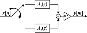
When you filter your signal, the IIR halfband decimator uses an efficient polyphase implementation for halfband filters. You can use the polyphase implementation to move the downsample operation before filtering. This change enables you to filter at a lower sampling rate.
IIR halfband filters are generally modeled using two parallel allpass filter branches.
Elliptic Design
The allpass filters for elliptic IIR halfband filter are given as
Quasi-Linear Phase Design
To achieve a near-linear phase response for IIR halfband filters, make one of the branches a pure delay. In this design, the cost of the filter increases.
The allpass filters for the quasi-linear phase IIR halfband filter are
where k is the length of the delay.
where N is the order of the IIR halfband filter.
You can represent filtering the input signal and then downsampling it by 2 using this figure.

Using the multirate noble identity for downsampling, you can move the downsampling operation before the filtering operation. This change enables you to filter at a lower rate.

To implement the halfband decimator efficiently, this algorithm replaces the delay block and downsampling operator with a commutator switch. When the first input sample is delivered, the commutator switch feeds this input to the first branch and the halfband decimator computes the first output value. As more input samples come in, the switch delivers one sample at a time to each branch alternatively. The decimator generates output every time the first branch generates an output. This halves the sampling rate of the input signal.
Analysis Filter Bank
The transfer function of the complementary highpass filter branch of the analysis filter bank is given by:
You can represent the analysis filter bank as in this diagram.

The IIR halfband decimator generates two power-complementary output signals by adding and subtracting the two polyphase branch outputs respectively.
For more information on filter banks, see Overview of Filter Banks.
To summarize, the IIR halfband decimator:
Decimates the input prior to filtering.
Acts as an analysis filter bank.
Has a nonlinear phase response and uses few coefficients with the elliptic design method.
Has near-linear phase response at the cost of additional coefficients with the quasi-linear phase design method, where one of the branches is a pure delay