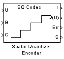
Scalar Quantizer Encoder
Encode each input value by associating it with index value of quantization region
Libraries:
DSP System Toolbox /
Quantizers
Description
The Scalar Quantizer Encoder block maps each input value to a quantization region by comparing the input value to the quantizer boundary points defined in the Boundary points parameter. The block outputs the zero-based index of the associated region.
Examples
Add a Scalar Quantizer
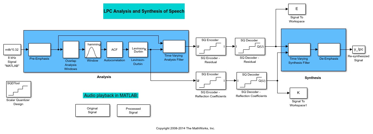
In this topic, you add scalar quantizer encoders and decoders to quantize the residual signal E and the reflection coefficients K:
Ports
Input
Specify the input data values as a vector or a matrix.
The input data, boundary points, codebook values, quantized output values, and the quantization error must have the same data type whenever they are present.
If the input is fixed point, it must be a signed integer or a signed fixed point value with a power-of-two slope and zero bias.
Data Types: single | double | int8 | int16 | int32 | fixed point
Specify the boundary points as a vector of length N. You must enter the boundary points in ascending order.
The input data, boundary points, codebook values, quantized output values, and the quantization error must have the same data type whenever they are present.
Dependencies
To enable this port, select Input port
from the Source of quantizer parameters
list.
Data Types: single | double | int8 | int16 | int32 | fixed point
Enter a vector of quantized output values that correspond to each index value. The length of the codebook vector must be N−1, where N is the length of the boundary points vector.
The input data, boundary points, codebook values, quantized output values, and the quantization error must have the same data type whenever they are present.
Dependencies
To enable this port, select Input port
from the Source of quantizer parameters list
and you select either the Output codeword or
Output quantization error check box.
Data Types: single | double | int8 | int16 | int32 | fixed point
Output
Index values, returned as a vector or a matrix of the same size as the input data.
The data type of this port depends on the setting of the Index output data type parameter.
Data Types: int8 | int16 | int32 | uint8 | uint16 | uint32
Quantized output values, returned as a vector or a matrix of the same size as the input data. These are the codeword values that correspond to each index value.
The input data, boundary points, codebook values, quantized output values, and the quantization error must have the same data type whenever they are present.
Dependencies
To enable this port, select the Output codeword parameter.
Data Types: single | double | int8 | int16 | int32 | fixed point
Quantization error, returned as a vector or a matrix of the same size as the input data. The quantization error is the difference between the input value and the quantized output value.
The input data, boundary points, codebook values, quantized output values, and the quantization error must have the same data type whenever they are present.
Dependencies
To enable this port, select the Output quantization error parameter.
Data Types: single | double | int8 | int16 | int32 | fixed point
Clipping status values, returned as a vector or a matrix of boolean values of the same size as the input data. Any time an input value is outside the range defined by the Boundary points parameter, the block outputs a 1 at the S port. When the value is inside the range, the blocks outputs a 0.
Dependencies
To enable this port, select the Output clipping status check box.
Data Types: Boolean
Parameters
Main Tab
Specify the source of quantizer parameters as one of these:
Specify via dialog–– Enter the boundary points and the codebook values using the parameters in the dialog box.Input port–– Specify the parameters using the block input ports. Input the boundary points and the codebook values using ports B and C, respectively.
Specify one of these partitioning methods to interpret the boundary points you enter:
Bounded–– Select this option to create a bounded quantizer.For example, when you enter these boundary points:
[0 0.5 3.7 5.8 6.0 11]
The block assigns any input values between 0 and 0.5 to index 0, input values between 0.5 and 3.7 to index 1, and so on. The block assigns any values that are less than 0 to index 0, the lowest index value. The block assigns any values that are greater than 11 to index 4, the highest index value.
Unbounded–– Select this option to create an unbounded quantizer.For example, when you enter these boundary points:
[0 0.5 3.7 5.8 6.0 11]
The block assigns any input values between 0 and 0.5 to index 1, input values between 0.5 and 3.7 to index 2, and so on. The block assigns any input values less than 0 to index 0 and any values greater than 11 to index 6.
Enter a vector of values in ascending order that represent the boundary points of the quantizer regions. These values are used to break up the set of input numbers into regions. Each region is specified by an index number.
Let N be the number of quantization regions. When
the codebook is defined as [c1 c2 c3 ... cN], and the
Boundary points parameter is defined as
[p0 p1 p2 p3 ... pN], then
p0<c1<p1<c2 ... p(N-1)<cN<pN for a
regular quantizer. When your quantizer is bounded, from the
Partitioning list, select
Bounded. You need to specify
N+1 boundary points, or [p0 p1 p2 p3 ...
pN]. When your quantizer is unbounded, from the
Partitioning list, select
Unbounded. You need to specify
N−1 boundary points, or[p1 p2 p3 ...
p(N-1)]. The block sets p0 equal to
−inf and pN equal to
inf.
Tunable: Yes
Dependencies
To enable this parameter, select Specify via
dialog from the Source of quantizer
parameters list.
Specify the searching method the block uses to determine the region in which the input value is located (quantizer index):
Linear–– The block compares the input value to the first region defined by the first two boundary points. When the input value does not fall within this region, the block then compares the input value to the next region. This process continues until the input value is determined to be within a region and is associated with the appropriate index value. The computational cost of this process is of the order P, where P is the number of boundary points.Binary–– The block compares the input value to the middle value of the boundary points vector. When the input value is larger than this boundary point, the block discards the boundary points that are lower than this middle value. The block then compares the input value to the middle boundary point of the new range, defined by the remaining boundary points. This process continues until the input value is associated with the appropriate index value. The computational cost of this process is of the order log2P, where P is the number of boundary points. In most cases, theBinaryoption is faster than theLinearoption.
Specify one of these actions to take when the input value is the same as the boundary point. This parameter determines the region to which the value is assigned.
Choose the lower index–– The block assigns the input value to the lower indexed region.Choose the higher index–– The block assigns the input value to the higher indexed region.
Select this check box to output the codeword values that correspond to each index value at port Q(U).
Select this check box to output the quantization error for each input value at port Err. The quantization error is the difference between the input value and the quantized output value.
Enter a vector of quantized output values that correspond to each index value.
If you set the Partitioning parameter to
Bounded and your boundary points vector
has a length of N, then you must specify a codebook
of length N−1. If you set the
Partitioning parameter to
Unbounded and your boundary points vector
has a length of N, then you must specify a codebook
of length N+1.
Tunable: Yes
Dependencies
To enable this parameter, select Specify via dialog from the
Source of quantizer parameters list and
select either the Output codeword or
Output quantization error check box.
Specify the output clipping status on the port S. Any time an input value is outside the range defined by the Boundary points parameter, the block outputs a 1 at this port. When the value is inside the range, the block outputs a 0.
Dependencies
To enable this parameter, set the
Partitioning parameter to
Bounded.
Specify one of these actions the block must take when an input value is outside the range defined by the Boundary points parameter:
ClipClip and warnError
Suppose the boundary points for a bounded quantizer are defined as
[p0 p1 p2 p3 ... pN] and the possible index
values are defined as [i0 i1 i2 ... i(N-1)], where
i0=0 and
i0<i1<i2<...<i(N-1). When you want
any input value less than p0 to be assigned to index
value i0 and any input values greater than
pN to be assigned to index value
i(N-1), select Clip. When you
want to be warned when clipping occurs, select Clip and
warn. When you want the simulation to stop and the
block to display an error when the index values are out of range, select
Error.
Dependencies
To enable this parameter, set the
Partitioning parameter to
Bounded.
Specify the data type of the index output from the block at port I as one of these:
int8uint8int16uint16int32uint32Inherit via back propagation
Data Types Tab
Specify the rounding mode for fixed-point operations as one of the following:
FloorCeilingConvergentNearestRoundSimplestZero
For more details, see rounding mode.
When you select this parameter, the block saturates the result of its
fixed-point operation. When you clear this parameter, the block wraps
the result of its fixed-point operation. For details on
saturate and wrap, see overflow
mode for fixed-point operations.
Block Characteristics
Data Types |
|
Direct Feedthrough |
|
Multidimensional Signals |
|
Variable-Size Signals |
|
Zero-Crossing Detection |
|
References
[1] Gersho, A. and R. Gray. Vector Quantization and Signal Compression. Boston: Kluwer Academic Publishers, 1992.
Extended Capabilities
C/C++ Code Generation
Generate C and C++ code using Simulink® Coder™.
Version History
Introduced before R2006a
See Also
Quantizer (Simulink) | Scalar Quantizer Decoder | Uniform Encoder | Uniform Decoder
MATLAB Command
You clicked a link that corresponds to this MATLAB command:
Run the command by entering it in the MATLAB Command Window. Web browsers do not support MATLAB commands.
选择网站
选择网站以获取翻译的可用内容,以及查看当地活动和优惠。根据您的位置,我们建议您选择:。
您也可以从以下列表中选择网站:
如何获得最佳网站性能
选择中国网站(中文或英文)以获得最佳网站性能。其他 MathWorks 国家/地区网站并未针对您所在位置的访问进行优化。
美洲
- América Latina (Español)
- Canada (English)
- United States (English)
欧洲
- Belgium (English)
- Denmark (English)
- Deutschland (Deutsch)
- España (Español)
- Finland (English)
- France (Français)
- Ireland (English)
- Italia (Italiano)
- Luxembourg (English)
- Netherlands (English)
- Norway (English)
- Österreich (Deutsch)
- Portugal (English)
- Sweden (English)
- Switzerland
- United Kingdom (English)

