IIR Halfband Stages in Multistage Filter Design
This example discusses IIR halfband stages in multistage decimators and interpolators.
Introduction
Rate conversion filters can be implemented efficiently using multistage decimators and interpolators, which are cascades of lowpass filters and downsampling or upsampling blocks. You can use the designRateConverter function to obtain such efficient multistage designs. These designs use FIR lowpass filters by default (usually a Kaiser window or an equiripple design). However, one can replace the FIR lowpass filters with IIR equivalents, as long as these IIR equivalents impart the same filter specifications as the FIR stages. Similar to the FIR multirate filters, IIR decimators and interpolators can be implemented efficiently using polyphase structures. IIR polyphase filters present several interesting advantages over FIR designs. These filters require a very small number of multipliers to implement, thus incur a smaller computational cost. They also have better gain response. The drawbacks presented by IIR designs are their nonlinear phase, and potential challenges if implemented in fixed-point, due to instability, sensitivity to quantization, and limit cycles problems. However, in some cases, those drawbacks of IIR designs can be addressed.
This example focuses on halfband stages of decimators, but this methodology can be generalized to higher rates, as well for interpolators.
Cost Efficiency Case Study
The computational cost of convolution filters is mostly affected by the number of multiplications needed on an average per input sample (MPIS). In this example, we measure MPIS count as the computational cost of a filter.
Multistage Halfband Standard FIR Design
As a case study, analyze a multistage decimator design with a decimation factor of 8, input sample rate of 9.6 kHz (resulting with an output sample rate of 1.2 kHz), an input bandwidth of 540 Hz, and a stopband attenuation 80 dB per stage. You can obtain an efficient multistage FIR decimator design using designRateConverter which returns a cascade of three FIR halfband decimators in this example.
MultistageFIRDecim = designRateConverter(DecimationFactor=8,...
                                        InputSampleRate=9.6e3,... % 9.6 kHz
                                        Bandwidth=540,...         % 540 Hz
                                        StopbandAttenuation=80,...
                                        Verbose=true)   % 80dB
designRateConverter(InterpolationFactor=1, DecimationFactor=8, InputSampleRate=9600, Bandwidth=540, StopbandAttenuation=80, MaxStages=Inf, CostMethod="estimate", OptimizeFor="MPIS", Tolerance=0, ToleranceUnits="absolute")

Conversion ratio: 1:8
Input sample rate: 9600
Output sample rate: 1200
MultistageFIRDecim =
  dsp.FilterCascade with properties:

         Stage1: [1×1 dsp.FIRDecimator]
         Stage2: [1×1 dsp.FIRDecimator]
         Stage3: [1×1 dsp.FIRDecimator]
    CloneStages: true
This default design achieves a computational cost of 12.875 MPIS on average. Use the cost function to determine the numerical cost of the designed filter cascade System object™.
cost(MultistageFIRDecim)
ans = struct with fields:
                  NumCoefficients: 69
                        NumStates: 126
    MultiplicationsPerInputSample: 12.8750
          AdditionsPerInputSample: 12
Halfband IIR Conversion
Given the cascade MultistageFIRDecim, replace every halfband decimator stage with an equivalent IIR design. The function redesignHalfbandStages(origDesign, DesignMethod) shipped with this demo replaces every halfband stage of the cascade origDesign with a dsp.IIRHalfbandDecimator System object design using the method specified in DesignMethod. The design method can be either "Elliptic" or "Quasi-linear phase".
First, use an elliptic design, which is the IIR equivalent of an optimal FIR equiripple filter. Elliptic designs produce the most efficient IIR halfband designs.
MultistageIIRDecim = redesignHalfbandStages(MultistageFIRDecim, "Elliptic");
cost(MultistageIIRDecim)
ans = struct with fields:
NumCoefficients: 11
NumStates: 17
MultiplicationsPerInputSample: 2.5000
AdditionsPerInputSample: 5
This method achieves computational cost of only 2.5 MPIS on average - more than 5x cheaper than the FIR design.
Magnitude Response Comparison
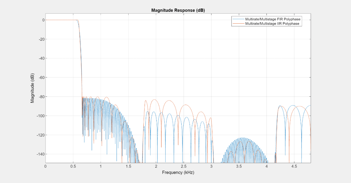
Overlay the magnitude responses of the FIR and IIR multirate multistage filters. The two filters look very similar and both meet the specifications.
FA = filterAnalyzer(MultistageFIRDecim,MultistageIIRDecim);

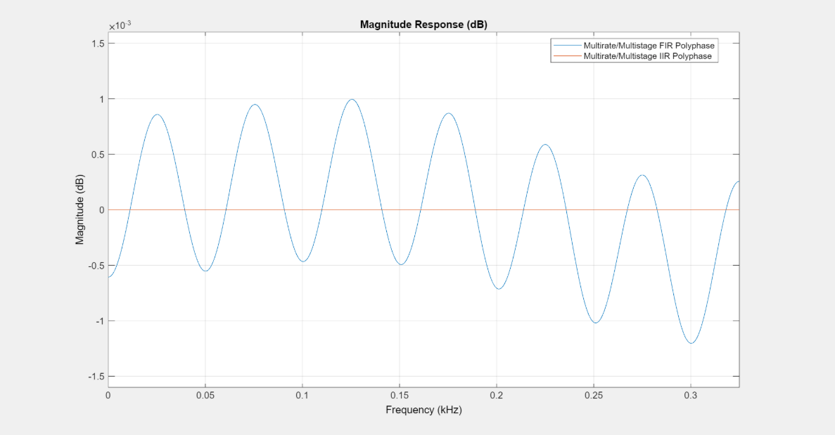
Close inspection actually shows the passband ripples of the IIR filter to be far superior to that of the FIR filter. So computational cost savings don't come at the price of a degraded magnitude response.
zoom(FA,"xy",[0 540 -0.0016 0.0016])
Quasi-Linear Phase Halfband IIR Designs
The drawback of IIR designs is their nonlinear phase, which may cause distortion. This can be largely mitigated by compensating for the nonlinear phase. It is possible to achieve almost linear phase response using specialized IIR design algorithms. The design method "Quasi-linear phase" of the dsp.IIRHalfbandDecimator achieves an almost linear phase response on the pass band of the filter.
In this method, the IIR halfband filter is implemented in a way that includes a pure delay connected in parallel with an allpass filter. This constraint on the implementation helps provide the quasi linear phase response (almost flat group delay). This implementation comes at the expense of a slight increase in the computational cost compared to the elliptic designs.
IIRLinearPhaseFilt = redesignHalfbandStages(MultistageFIRDecim, "Quasi-linear phase");
cost(IIRLinearPhaseFilt)
ans = struct with fields:
NumCoefficients: 25
NumStates: 55
MultiplicationsPerInputSample: 4.3750
AdditionsPerInputSample: 8.7500
Although not as efficient as the elliptic case, the design is far more efficient than using FIR halfband filters.
Group Delay Comparison
Overlaying the group delay of the three designs, and focusing on the passband of the filters (the area of interest), we can verify that the latter IIR design achieves a nearly flat group delay in that area. In contrast, the elliptic filter, while more efficient (and with a lower group delay overall), has a clearly nonlinear phase response.
FA = filterAnalyzer(MultistageFIRDecim, MultistageIIRDecim, IIRLinearPhaseFilt, Analysis='groupdelay');
zoom(FA,"XY",[0 0.125 0 225]);

Summary
One can choose either FIR or IIR for multirate designs, depending on the problem specification and requirements. Each approach has its own benefits and drawbacks.
IIR filters have traditionally been considered numerically efficient to meet a given set of specifications, much more than their FIR counterparts. They also offer better magnitude response. On the downside, they present a nonlinear phase (which results in a distortion), and could be numerically sensitive.
In contrast, FIR filters can provide a linear-phase response along with robust numerical behabior (especially in fixed point implementations). However, they are more computationally costly, and suffer from inferior magnitude response compared to IIR filters.
Utilizing special structures (such as polyphase techniques) can bridge the gaps between the two approaches. Polyphase FIR filters are more computationally efficient than single-phase. Similarly, polyphase IIR filters enjoy most of the advantages that FIR filters have (numerical stability and near flat group delay) while remaining computationally cheap.