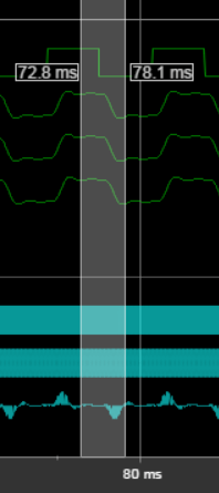
Inspect and Measure Transitions Using the Logic Analyzer
In this tutorial, you explore key functionality of the Logic Analyzer, such as choosing and configuring signals to visualize, stepping through a simulation, and measuring transitions.
Open a Simulink Model
To follow along with this tutorial, open the dspsdadc_fixpt
model in the Sigma-Delta A/D Conversion example.

Open the Logic Analyzer
From the Simulink® toolstrip, on the Simulation tab, in the Review
Results gallery, click the Logic Analyzer button ![]() .
.
The Logic Analyzer opens with the selected signals shown in the channel display.

Configure Global Settings and Visual Layout
Click Settings. Set the Height to 20 and the Spacing to 10, and then click OK.
From the Logic Analyzer toolstrip, click Add Divider. A divider named
Divideris added to the bottom of your channels. You can use dividers to separate signals.Double-click
Dividerand renameDividerasAnalog Input Calculation. Drag the divider to the top of the channels pane.Add another divider and name it
Error Calculation.From the Logic Analyzer toolstrip, click Add Group. A group named
Group1is added to the bottom of your channels. You can use groups to group signals in a collapsible tree structure. Double-clickGroup1and rename it asDigital Approximation Calculation.You can visualize the same signal in multiple places. Right-click the
Analog Input(Delayed)signal and select Copy. Paste this signal under theError Calculationdivider. Repeat the process for theCIC Digitized Approximationsignal. Organize your dividers and signals as shown in the screen shot, and then collapse theDigital Approximation Calculationgroup.

Set Stepping Options
From the Logic Analyzer toolstrip, click Stepping Options.
Select the Enable stepping back option. Specify the Maximum number of saved back steps as
2and the Interval between stored back steps as100steps. When you run the simulation, a snapshot of the model is taken every 100 steps. Only the last snapshot is saved.Set Move back/forward by to
100steps.Select the Pause simulation when time reaches option. Specify the simulation to pause after
0.2seconds of model time has elapsed, and then click OK.
Run Model
To run the model, click Run on the Logic Analyzer toolstrip. The model runs for 0.2 seconds of model time and then pauses.
Click
 to fit your data to the time range.
Configure Individual Wave Settings
Select all waves under your
Analog Input Calculationdivider. Then on the Waves tab, select a new Wave Color for the selected waves.Under the
Error Calculationdivider, select theAnalog Input(Delayed)andCIC Digitized Approximationwaves. On the Waves tab, modify the Format toDigital. The selected waves are now displayed as digital transitions.
Inspect and Measure Transitions
On the Logic Analyzer toolstrip, click
 and then drag-and-drop start and end points to zoom in time.
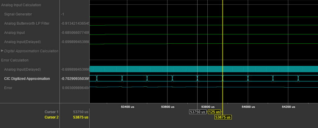
For waves displayed as digital, you can use the Next Transition and Previous Transition buttons. To move the active cursor to the next transition, click Next Transition.
Click Lock to lock the active cursor in place.
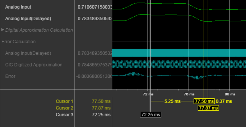
Click Add Cursor to add another cursor to the axes. The cursor shows its current position in time, and the difference from all surrounding cursors in time.

Right-click the second cursor you added and select Delete Cursor.
Press the space bar to zoom out.
Add another cursor and line it up with a low point of the
Analog Inputwave in yourAnalog Input Calculationdivision. Use the value displayed in the wave value pane to fine-tune the cursor position in time.Add another cursor and line it up with the corresponding low point of the
Analog Input(Delayed)wave in yourAnalog Input Calculationdivision.
Step Through Simulation
To move the simulation forward 100 steps, click Step Forward. The time axis adjusts so that you can see the most recent data.
To move the simulation backward 100 steps, click Step Back. The Step Back button becomes disabled because you specified saving only two back step.
Save Logic Analyzer Settings
When you save your model, the logic analyzer settings are also saved for that model.