Verify Numerical Accuracy Using PIL
In a processor-in-the-loop (PIL) simulation, the generated code runs on an embedded processor or QEMU emulating an embedded processor. The results of the PIL simulation are transferred to Simulink® to verify the numerical equivalence of the simulation and the code generation results. The PIL verification process is a crucial part of the design cycle to check that the behavior of the generated code matches the design. For more information PIL simulations, see SIL and PIL Simulations.
For versions of these work flows for ARM® Cortex®-A based processors, see Code Verification and Validation with PIL and External Mode.
PIL Verification Using PIL Block
When performing PIL verification using a block:
You can verify code generated for subsystems.
You can verify numerical equivalence by comparing the signals of the two blocks
You must provide a test harness model to supply test vector or stimulus inputs.
You must swap your original subsystem with a generated PIL block. Do not save your model in this state, or you will lose your original subsystem.
For more information PIL verification with blocks, see Choose a SIL or PIL Approach.
To create and test a subsystem block using an equivalent PIL block, follow this workflow:
Create a new model and name it
TestHarness.Configure the model for the ARM Cortex-A processor following the steps in Configure a Model for ARM Cortex-A9 QEMU Emulator.
On the Hardware tab, click Hardware Settings.
In the Configuration Parameters dialog box, set Code Generation > Verification > Advanced parameters > Create block to
PIL. Click OK.Add a Subsystem block to the model and name it
Controller.Create a test harness. For example, you can:
Connect to a shared plant model.
Use parallel inputs for the Subsystem and PIL blocks.
Use a Sum block (Add) to compare the outputs for differences.
Connect the output of the Sum block to a Scope block to display the numerical differences.
Use a Manual Switch block to toggle between the outputs of the two blocks.
This sample
TestHarnessmodel is missing a PIL block.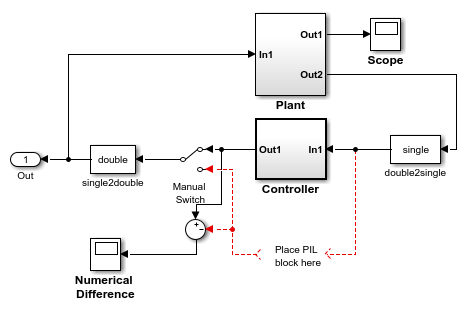
Right-click the
ControllerSubsystem block and select Block Parameters (Subsystem).In the Subsystem dialog box, select Treat as atomic unit.
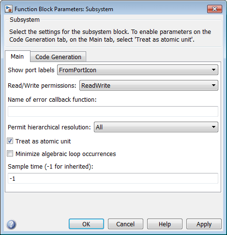
Place or create the model that you want to test within the Subsystem block.
Right-click the Subsystem block and select C/C++ Code > Build This Subsystem.

The model,
untitled*, contains a PIL block named after the subsystem.
Copy the PIL block from
untitled*to the test harness model.
Close
untitled*without saving it.Set Simulation mode to
Normal.
Click Run to start the PIL simulation.

In a PIL simulation, the test harness model executes in Simulink software while the PIL block executes on the embedded processor. The simulation lasts for the duration specified by the Simulation stop time. During the simulation, you can:
Use the Manual Switch to toggle between the two outputs.
Observe the scope for numerical differences.
Perform PIL Verification Using Model Block PIL
When performing PIL verification using a model block:
You can verify code generated for referenced models.
You can verify that the outputs of the blocks are numerically equivalent.
You can easily switch a model block between the normal and PIL simulation mode.
You must provide a test harness model to supply test vector or stimulus inputs.
For more information, see Model.
To create and test a subsystem block using Model Block PIL, follow this workflow:
Create the referenced model that you want to verify using PIL simulation.
Create a test model on which to run the PIL simulation.
Configure both the referenced model and test model for the ARM Cortex-A processor by following the steps in Build and Run an Executable on the ARM Cortex-A9 QEMU Emulator.
Note
You must maintain the same model Configuration Parameter values for both the referenced model and the test model. To share a configuration between the two models, see Share a Configuration with Multiple Models.
Add a Model block to the test model that points to your referenced model, as described in Reference Existing Models.
Copy and paste the Model block so the test model contains two identical Model blocks.
Create parallel inputs and outputs for the Model blocks.

Right-click one of the Model blocks, and select Block Parameters (ModelReference).

In the Block Parameters dialog box, set Simulation mode to
Processor-in-the-Loop (PIL)and set Code Interface toModel reference. Click OK.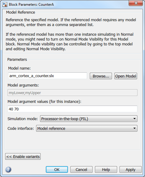
Leave the Simulation mode of the test model and the other Model block set to
Normal.
Click Run.

In this simulation, the test model and one Model block execute in Simulink software while the Model block that you configured to use PIL executes on the embedded processor. The simulation lasts for the duration specified by the Simulation stop time.
PIL Verification Using PIL Simulation for Top Models
When performing PIL verification using top–model simulation:
You can verify code generated for a top model.
You can record PIL simulation data from your model.
You can review PIL simulation data using the Simulation Data Inspector.
You can switch the entire model between normal and PIL simulation mode.
You must configure the model to load test vectors or stimulus inputs from the MATLAB® workspace.
To create and test a top-model PIL simulation, follow this workflow:
Create the test model that you want to verify.
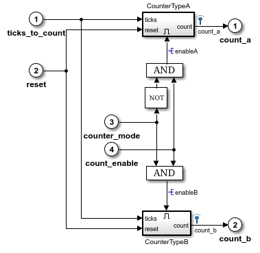
Configure the model for the ARM Cortex-A processor by following the steps in Build and Run an Executable on the ARM Cortex-A9 QEMU Emulator.
Set Simulation mode to
Processor-in-the-Loop (PIL).
Click the Simulation Data Inspector button arrow, and enable Send Logged Workspace Data to Data Inspector.
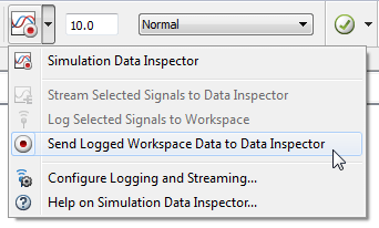
Click Run.

The test model simulates in PIL mode on the embedded processor. The simulation lasts for the duration specified by the Simulation stop time.
When the PIL simulation stops, click Simulation Data Inspector to review the PIL data.