Generate Code and Deploy Using SoC Builder
Hardware boards and devices supported by MathWorks® require additional configuration and setup steps to connect to MATLAB® and Simulink®. Each support package provides a hardware setup process that guides you through registering, configuring, and connecting to your hardware board.
This tutorial shows how to build hardware and software executables for your model and execute your application. After you create an SoC model by using the multiple cores of Infineon® AURIX™ microcontroller, use the SoC Builder tool to generate executables, code, and program the hardware board.
Prepare Model for Generation
Open the application model and select a starting point for the build process.
To launch the SoC Builder tool, navigate to Configure, Build, Deploy & Start, Configure & Build, or Configure, Monitor & Tune. The SoC Builder tool guides you through series of steps depending on the choice of build options.
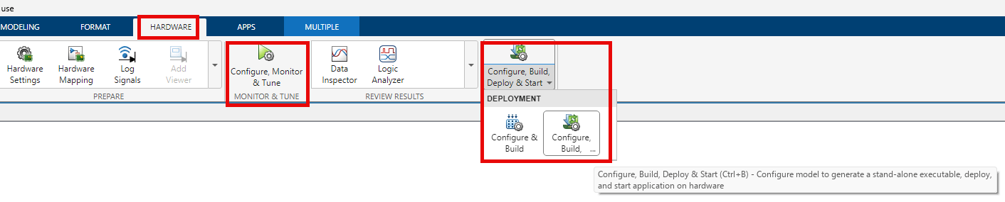
Select one of these build actions for your model and automate the build process.
Configure, Build, Deploy & Start— Select this option to generate code and build software executables for your model. After building, the SoC Builder loads the generated code to the Infineon AURIX board and executes the application.
Configure & Build — Select this option to generate code and build software executables for your model. The SoC Builder saves the generated binaries in a folder, and you can continue the execution later.
Configure, Monitor & Tune — Select this option to build the model and run it in external mode. Use external mode to tune parameters of the application model without having to rebuild the model. You can also log data from the hardware board and display it on the host computer. For more information on external mode of simulation, see External Mode Simulations for Parameter Tuning, Signal Monitoring, and Code Execution Profiling.
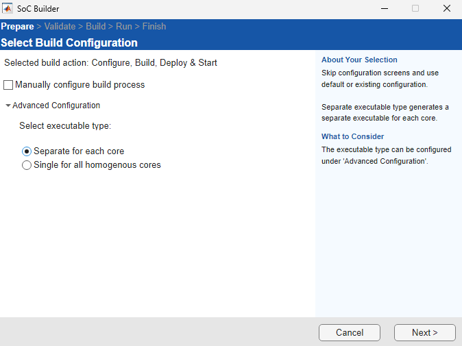
Manually configure build process — Disable this option to build your model with fewer clicks. Automating the build process performs these actions.
Skips these steps: select project folder, review hardware mapping
Runs these steps : validate model, build model, and run application
All these steps use the inputs that you provided in the most recent build. If you are running the build process for the first time, SoC Builder tool uses default inputs for these steps.
Advanced configuration — Select the executable type as one of these options.
Separate for each core (default) — Generate separate executables for each participating core of the application model.
By default, the SoC Builder tool generates separate executables for all the participating TriCores in the external mode of simulation.
Single for all homogenous cores — Generate single executables for all homogenous TriCores used in the application model.
Use custom linker file — Select this option to provide your own custom linker file, which you can specify in the Linker file path using the Browse button.
You must select the Single for all homogenous cores parameter to use Use custom linker file option.
After you specify the build options, click Next.
Select Project Folder
Specify a path to a project folder by entering the path in the Project Folder text box or by browsing to a folder location. SoC Builder places all the generated files, including reports, executables, and the bitstream in this specified folder.
Click Next.
Review Hardware Mapping
Open the Hardware Mapping tool by clicking View/Edit.
View and edit the peripherals and task mapping in the Mapping Browser of the Hardware Mapping tool.
The Tasks entry in the Mapping Browser pane is enabled only if you have an event-driven task defined in the Task manager block in your top model.
Review the peripheral parameters for your hardware board, and edit them if you need to.
The Peripherals entry in the Mapping Browser pane is enabled only if you have a peripheral block in your model hierarchy.
Click Next.
Select External Mode on CPU
You can view this step if you choose to build the model in Configure, Monitor & Tune mode of simulation.
The SoC Builder lists the participating cores of your application model. Select a specific core from the available cores for external mode of simulation.
Click Next.
Validate Model
Check the compatibility of the model against the selected board by clicking Validate.
On the right pane, view the generated report containing the system status, board properties, and generated code.
Click Next after successful completion of the model validation.
Build Model
Generate a compiled executable for your software by clicking Build.
Click Next after successfully building the model.
Load and Run Application
Verify that your board is connected to the host computer via an Ethernet cable and click Load and Run. This action loads the generated code to the Infineon AURIX hardware board, programs the microcontroller, and runs the application.
If you select Configure, Monitor & Tune in the Prepare the Model for Generation step, this action loads the generated code to the hardware board and opens the model in external mode. You can now choose signals for logging and monitoring or change the tunable parameters.