Main Content

Analog to Digital Converter

Convert analog signal on ADC input pin to digital signal

Since R2021b

Add-On Required: This feature requires the Embedded Coder Support Package for STMicroelectronics STM32 Processors add-on.

  • Analog to Digital Converter block

Libraries:
Embedded Coder Support Package for STMicroelectronics STM32 Processors / STM32F2xx Based Boards
Embedded Coder Support Package for STMicroelectronics STM32 Processors / STM32F3xx Based Boards
Embedded Coder Support Package for STMicroelectronics STM32 Processors / STM32F4xx Based Boards
Embedded Coder Support Package for STMicroelectronics STM32 Processors / STM32F7xx Based Boards
Embedded Coder Support Package for STMicroelectronics STM32 Processors / STM32G4xx Based Boards
Embedded Coder Support Package for STMicroelectronics STM32 Processors / STM32H7xx Based Boards
Embedded Coder Support Package for STMicroelectronics STM32 Processors / STM32L4xx Based Boards
Embedded Coder Support Package for STMicroelectronics STM32 Processors / STM32L5xx Based Boards
Embedded Coder Support Package for STMicroelectronics STM32 Processors / STM32U5xx Based Boards
Embedded Coder Support Package for STMicroelectronics STM32 Processors / STM32WBxx Based Boards

Description

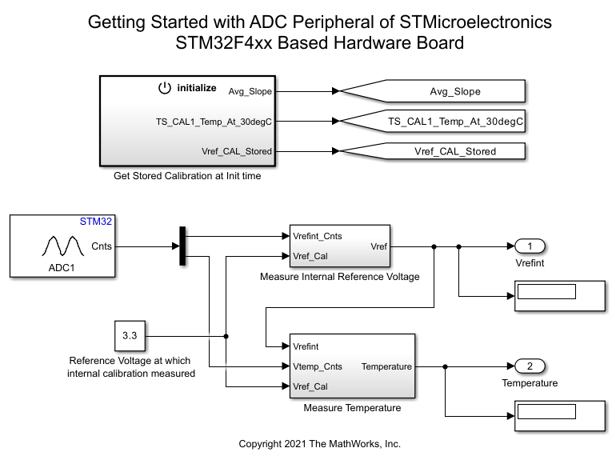
Use the Analog to Digital Converter block to convert the analog value at an ADC input pin to a digital value. The block output is a 1-by-N row vector depending on the number of conversions N. The block measures the voltage of an analog pin relative to the analog input reference voltage on STM32 Processor Based Boards.

The conversion time for ADC channels is configured in the STM32CubeMX project.

For STM32H7xx based board and STM32G4xx based board, the input channels for the ADC block can be configured in STM32CubeMX project to either Differential mode or Single-ended. User can specifying the offset value for the selected channel in the STM32CubeMX project.

For more information, see Processing the ADC Data for STM32H7xx and STM32G4xx Based Boards.

Note

In a model use STM32H7xx based board library blocks with STM32H7xx based target hardware board only. When you run a model with STM32 library blocks mapped to STM32H7xx Based target you will encounter with an error message.

Note

You can run a Simulink® model containing PWM Output block in Connected IO mode on STM32 Processor Based Boards.

Examples

Ports

Input

expand all

Convert analog signal on ADC input pin to digital signal.

Triggers the ADC input pin for conversion.

  • 1 - ADC start of conversion is triggered

  • 0 - ADC start of conversion is not triggered

Dependencies

To enable this port, set the Trigger mode parameter to Trigger only.

Data Types: Boolean

The simulation-only message input port, when connected to an ADC Interface (SoC Blockset) block, acts as pass-through with the input to the ADC Interface block emitted on the output of the Analog to Digital Converter Block block during simulation.

Dependencies

To enable this port, enable the Enable simulation port parameter.

Data Types: SoCData

Output

expand all

The block outputs the digital values of selected analog channels converted from Analog to Digital Converter (ADC) as a 1-by-N vector, where N is number of conversions.

Dependencies

To enable this port, set the Trigger mode parameter to either Trigger and read or Read results only.

Data Types: uint16

The block outputs the ADC block status.

When the trigger mode is Trigger and Read or Read results only the block outputs the following status:

  • 0 - output counts are valid

  • 1 - output counts are not available or overrun flag is set.

When the trigger mode is Trigger only the block outputs the following status:

  • 0 - when ADC is triggered

  • 1 - when ADC is not triggered

Dependencies

To enable this port, select the Output status parameter.

Data Types: uint16

Parameters

expand all

Select the ADC module for conversion.

Select one of the following options for conversion:

  • Injected group — You can convert up to four analog signals. In this mode, you can inject the ADC conversion during the conversion of regular group channels.

  • Regular group — You can convert up to 16 analog signals.

Select one of these option to trigger the conversion.

  • Trigger and read — Select this option to trigger ADC start of conversion at every sample time. The block output waits until the conversion is complete and emits the results. This option enables the output port Cnts.

  • Trigger only — Use this option to read the ADC conversion results in triggered or enabled subsystems. As the block does not show the conversion results in this mode, use another Analog to Digital Converter block with the Trigger mode parameter set to Read results only to display the conversion results.

  • Read results only — Select this option to read the newly converted ADC data. If no new data is available, the block outputs the status as 1. This option also enables the output port Cnts.

Set the number of ADC conversions based on the conversion group you select in the Conversion group parameter.

  • Inject group - Specify a number between 1 to 4.

  • Regular group - Specify a number between 1 to 16.

When you select this parameter, the block configures Status output port. The Status port outputs the status of the ADC conversion.

Dependencies

To enable the Output status parameter, set the Trigger mode parameter to either Trigger and read or Read results only.

Specify how often (in seconds) the block reads the pin value. Enter a value greater than zero. When you specify this parameter as -1, Simulink determines the best sample time for the block based on the block context within the model.

Dependencies

To enable the Sample time parameter, set the Trigger mode parameter to either Trigger and read or Read results only.

Select this parameter to add an SoC Blockset compatible simulation output port.

More About

expand all

Processing the ADC Data for STM32H7xx and STM32G4xx Based Boards

Extended Capabilities

C/C++ Code Generation
Generate C and C++ code using Simulink® Coder™.

Version History

Introduced in R2021b