Getting Started with STM32H7xx-Based Dual-Core Boards
This example shows how to use the Embedded Coder® Support Package for STMicroelectronics® STM32 Processors to run a Simulink® model on a STM32 H7xx-based dual-core board.
Introduction
In this example, you learn:
How to configure a Simulink model to generate code and toggle an LED light on the board using the ARM-Cortex M7 and ARM-Cortex M4 cores individually.
Configure Simulink model using both cores together (Cortex-M7 as primary core and Cortex-M4 as the secondary core).
Prerequisites
Required Hardware
STM32 Nucleo-H745ZIQ board
Micro USB cable
Jumper cable
Available Models
Blink LED using Cortex-M7 core
1. Open the m7_led_blink.slx model.
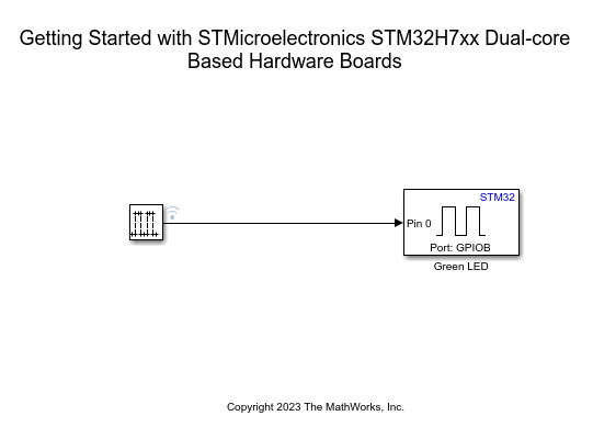
2. Configure the GPIO block. The green LED is connected to Pin 0 of the GPIOB port in the Green LED block.
Model Configurations
Open the Modeling tab and press CTRL+E to open the Configuration Parameters dialog box. Go to Hardware Implementation > Hardware board.
Select STM32H7xx Based (Dual-core).
Select an existing STM32CubeMX project or create a new one by completing the steps in the Getting Started with STMicroelectronics STM32 Processor Based Boards.
Select the Cortex-M7 core from the CPU core. Make sure that the Enable other core option is disabled.

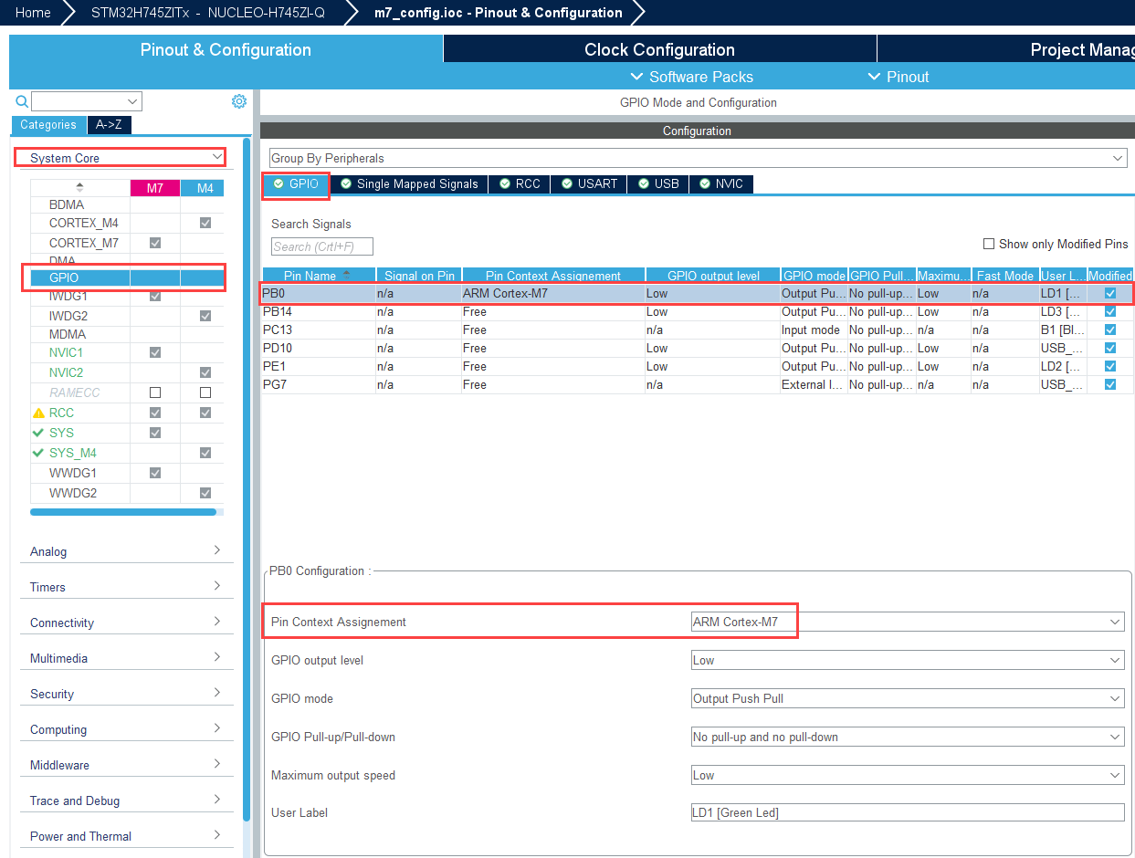
Configuring STM32CubeMX Project
Open the
m7_config.iocfile.Configure the PB0 pin as GPIO Output.
Set Pin Context Assignment to ARM Cortex-M7.
Generate Code and Deplot to Hardware Board from Simulink Model
1. To generate the code for the model, press Ctrl+B or click Build, Deploy & Start.
2. Follow the build process by opening the diagnostic viewer using the link provided at the bottom of the model canvas. After you load the code on the board, the green LED blinks on the hardware board, indicating that the code is running.
Blink LED using Cortex-M4 core
To blink the LED using the M4 core, complete the steps described in the Blinking an LED using the Cortex-M7 core section. Verify these configurations in m4_led_blink.slx model.
STM32CubeMX Project:
In the m4_config.iocfile, set Pin Context Assignment of PB0 to ARM Cortex-M4.Configuration Parameters: Set CPU core to Cortex-M4.
Run the
m4_led_blink.slxmodel and observe the green LED blinking on the hardware board, indicating that the code is running.
Blink LED using both Cores (Cortex-M7 as primary and Cortex-M4 as secondary)
In this section, you toggle the PD7 GPIO pin from the Cortex-M7 core. PD7 is connected to PD6 with a jumper cable. In the Cortex-M4, the PD6 is configured to generate an interrupt at every rising edge of PD7. In the interrupt service routine of PD6, the yellow LED o board is set to toggle every time you trigger an interrupt.
The Cortex-M7 core is configured as the primary core. It performs system initialization and then boots the Cortex-M4 core, which is configured as the secondary core.
Configure and Deploy Primary Core Model
1. Open the m7_gpio_toggle.slx model.
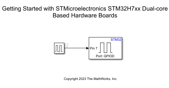
2. Configure the GPIO block by setting the port to GPIOD and the pin to 7 (PD7).
3. Open the Configuration Parameters and create or select the STM32CubeMX project.
4. Select Cortex-M7 from the CPU core.
5. Select the Enable other core option and enable Initialize system clock and configure selected core as main core.
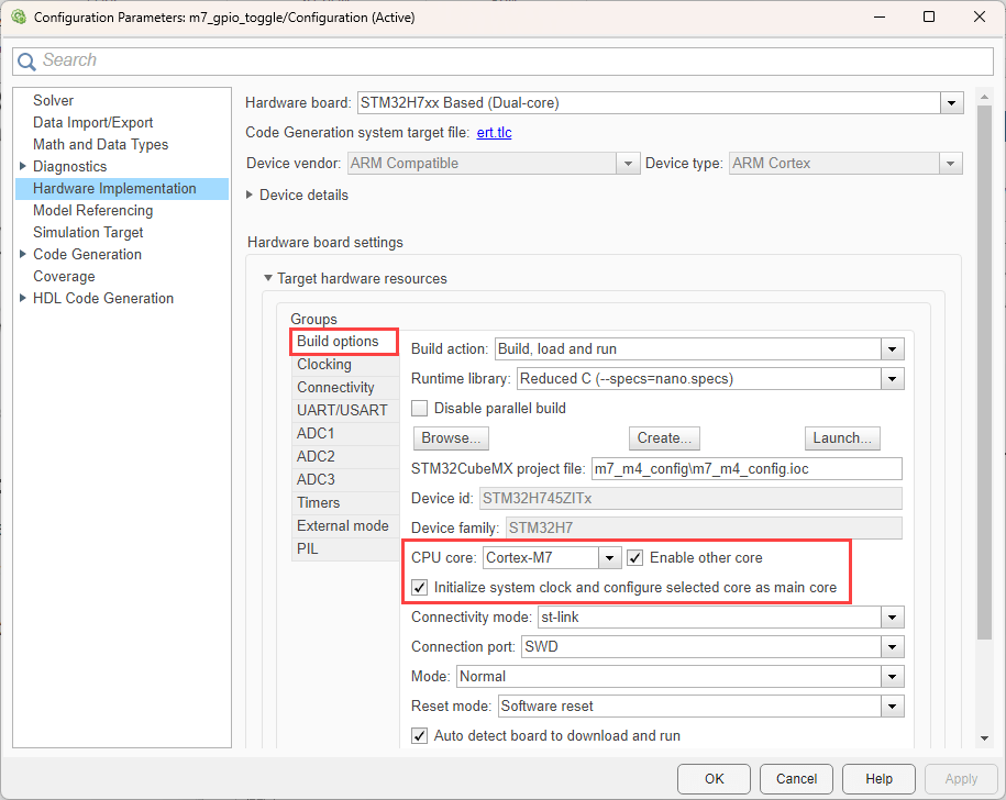
6. Configure the PD7 pin as GPIO Output in STM32CubeMX and set its Pin Context Assignment to Cortex-M7.
7. Deploy the model.
Configure and Deploy Secondary Core Model
1. Open the M4_led_toggle.slx model.

2. PD6 triggers the EXTI6 event. EXTI6 is handled via the EXTI9_5_IRQHandler. Select the same from the hardware interrupt block.
3. Configure the GPIO block in the Function-Call subsystem. The yellow LED is connected to the PE1 pin. Select the same in the GPIO block.
4. Open the Configuration Parameters and create or select the STM32CubeMX project.
5. Select Cortex-M4 from the CPU core.
6. Select the Enable other core option and disable Initialize system clock and configure selected core as main core. Since the Cortex-M7 core performs system initialization, the Cortex-M4 core does not have to initialize the system.
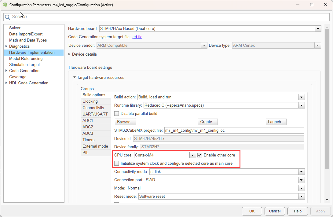
7. Configure the PD6 pin as GPIO EXTI in STM32CubeMX and set its Pin Context Assignment to Cortex-M4. Configure the PE1 yellow LED pin as GPIO Output and set its Pin Context Assignment to Cortex-M4.
8. Click Build, Deploy & Start.
The yellow LED now starts blinking at half the rate of the frequency of the pulse generator which is the rate at which PD7 toggles.
Significance of Enable other core option
1. You can choose if you want the selected core to be the main core, thus doing the system initialization such as system clock configuration. This can be done by selecting the Initialize system clock and configure selected core as main core checkbox.
2. The enable other core option is used to check if core synchronization is required or not:
If the selected core is not set as main core, then selecting Enable other core will deploy the model to the selected core and then disable the same. At the same time the selected core is disabled, the other core is enabled. The other core is expected to be the main core, and is expected to boot the secondary core.
If the selected core is set as main core, then selecting Enable other core will deploy the model to the selected core, and the selected core will also boot the other core. The other core is expected to be set as the secondary core.
3. If Enable other core is unchecked, only one core boots, and the other core will be disabled.