Hall Offset Calibration for PMSM with STM32 Processors
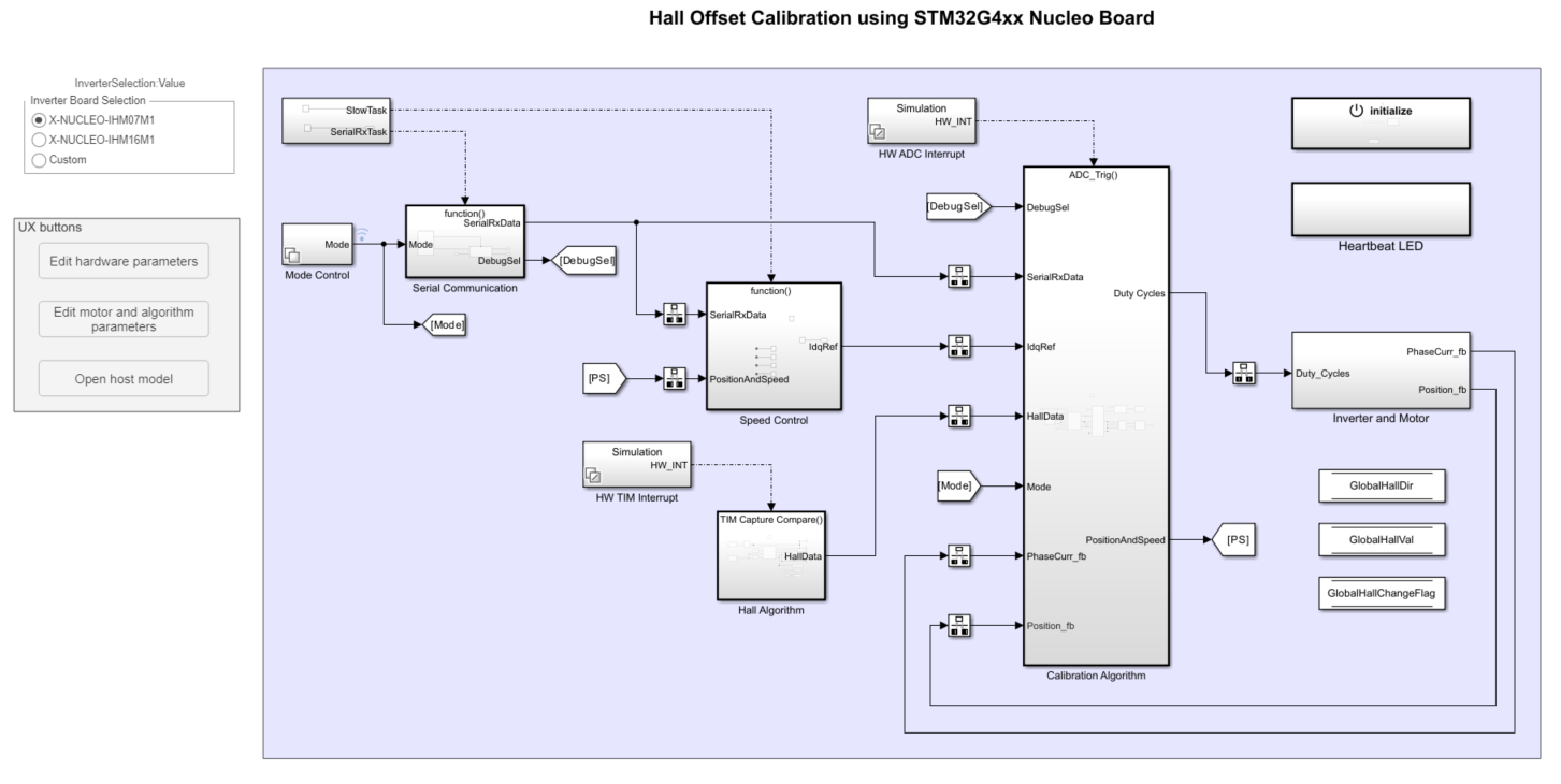
This example calculates the offset between the rotor direct axis (d-axis) and position detected by the Hall sensor. The field-oriented control (FOC) algorithm needs this position offset to run the permanent magnet synchronous motor (PMSM) correctly. To compute the offset, the target model runs the motor in the open-loop condition. The model uses a constant (voltage along the stator's d-axis) and a zero (voltage along the stator's q-axis) to run the motor (at a low constant speed) by using a position or ramp generator. When the position or ramp value reaches zero, the corresponding rotor position is the offset value for the Hall sensors.
The control algorithm (available in the field-oriented control and parameter estimation examples) uses this offset value to compute an accurate position of d-axis of the rotor. The controller needs this offset to optimally run the PMSM.
Required Hardware
This example requires the following hardware:
A Nucleo-STM32G431RB board.
X-NUCLEO-IHM07M1 or X-NUCLEO-IHM16M1 driver expansion board.
BLY172S-24V-4000 - Brushless DC Motor
Available Models
This example includes these models:
The target models can be used for code generation. The host models are run as a simulation and communicate with the target hardware to control the motor.
open_system('STM32_HallOffset_Target');
Generate Code and Deploy Model to Target Hardware
This section instructs you to generate code and run the motor by using open-loop control.
This example uses a host and a target model. The host model is a user interface to the controller hardware board. You can run the host model on the host computer. The prerequisite to use the host model is to deploy the target model to the controller hardware board.
The host model uses serial communication to command the target model and run the motor in an open-loop configuration. You can use the host model to control the motor rotations and validate direction of rotation of the motor. The host model displays the calculated offset value.
Generate Code and Run Model on Target Hardware
Complete the hardware connections as explained in the Field-Oriented Control of PMSM with Hall Sensor Using STM32G4xx Based Processors.
Ensure the motor parameters are updated. For more information, see Estimate PMSM Parameters Using Custom Hardware (Motor Control Blockset).
The model automatically calculates the Analog-to-Digital Converter (ADC) or current offset values. To disable this functionality (enabled by default), update the value to 0 in the
inverter.ADCOffsetCalibEnablevariable in the model initialization script. Alternatively, you can compute the ADC offset values and update it manually in the model initialization scripts. For instructions, see <Open-Loop Control of 3-Phase AC Motors Using STM32 Processor Based Boards>.Open the target model and select the desired inverter board.
Click Build, Deploy & Start on the Hardware tab to deploy the model to the hardware.
In the target model, click the host model button to open the host model.
For details about the serial communication between the host and target models, see Host-Target Communication.
In the model initialization script associated with the target model, specify the communication port using the variable target.comport. The example uses this variable to update the Port parameter of the Host Serial Setup, Host Serial Receive, and Host Serial Transmit blocks available in the host model.
Click Run on the Simulation tab to run the host model.
Motor calibration will begin.
The receive subsystem will display the current status of calibration and the calculated value in radians.
Note: To immediately stop the motor, click the Emergency Motor Stop button.