Main Content

Field-Oriented Control of PMSM with Hall Sensor Using STM32G4xx Based Processors

This example implements the field-oriented control (FOC) technique to control the speed of a three-phase permanent magnet synchronous motor (PMSM). The FOC algorithm requires rotor position feedback, which is obtained by a Hall sensor.

A closed-loop FOC algorithm is used to regulate the speed and torque of a three-phase PMSM.

This example uses STM32G4xx Based peripheral blocks from the Embedded Coder® Support Package for STMicroelectronics® STM32 Processors and MCB library blocks from Motor Control Blockset™.

The Hall sensor is used to measure the rotor position. A Hall effect sensor varies its output voltage based on the strength of the applied magnetic field.

A PMSM consists of three Hall sensors located electrically 120 degrees apart. A PMSM with this setup can provide six valid combinations of binary states (for example, 001,010,011,100,101, and 110).

The sensor provides the angular position of the rotor in the multiples of 60 degrees, which the controller uses to compute the angular velocity.

The controller can then use the angular velocity to compute an accurate angular position of the rotor.

Required Hardware

This example requires the following hardware:

  • A Nucleo-STM32G431RB board.

  • X-NUCLEO-IHM07M1 or X-NUCLEO-IHM16M1 driver expansion board.

  • BLY172S-24V-4000 - Brushless DC Motor

Hardware Connections

The connections for the X-Nucleo-IHM16M1 inverter board are shown below:

Available Models

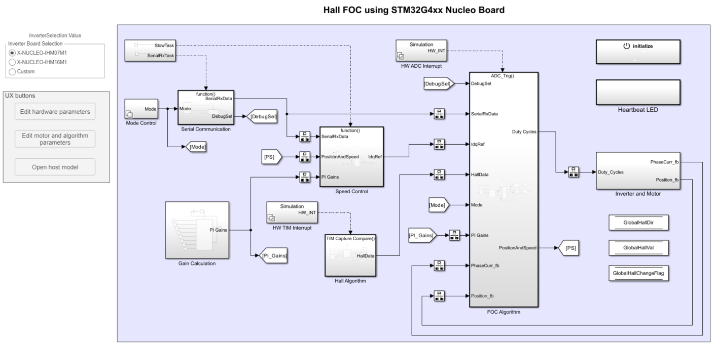
This example includes these models:

The target models can be used for both code generation and simulation.

The host models are run as a simulation and communicate with the target hardware to control the motor. You can use the open_system command to open the Simulink models. For example:

open_system('STM32_HallFOC_Target');

Prerequisites

Before deploying the model onto hardware, complete the following tasks:

  1. Update the target hardware device COM port in the STM32MotorControlData script. This script can be accessed via the Edit hardware parameters button.

  2. Obtain the motor parameters. Default motor parameters are provided which can be replaced by values from either the motor datasheet or other sources. However, if you have the motor control hardware, you can estimate the parameters for the motor that you want to use, by using the Motor Control Blockset parameter estimation tool. For more information, see Estimate PMSM Parameters Using Recommended Hardware (Motor Control Blockset).

  3. If you obtain the motor parameters from the datasheet or other sources, update the motor parameters and inverter parameters in the model initialization script associated with the Simulink® models. To quickly access this script, click on the Edit motor and algorithm parameters button in the model.

  4. Update the hall offset value in the model initialization script. If the hall offset is not known, run the hall offset calculation model first. The calculated offset is displayed in the host model after calibration has been completed. The calculated value must be updated in the pmsm.PositionOffset variable in the script. For more information, see Hall Offset Calibration for PMSM with STM32 Processors.

You can use this command to open the offset calculation target model:

open_system('STM32_HallOffset_Target');

Configure the Model

1. Open the STM32_HallFOC_Target model. This model is configured for STM32G4 xx Based hardware.

2. To run the model on other STM32 based-boards, first press Ctrl+E to open the Configuration Parameters dialog box. Then, select the required hardware board by navigating to Hardware Implementation > Hardware board.

3. Go to Build options and click Browse to select the STM32CubeMX project file.

Peripheral Configuration

STM32CubeMX Configurations

ADC Configuration

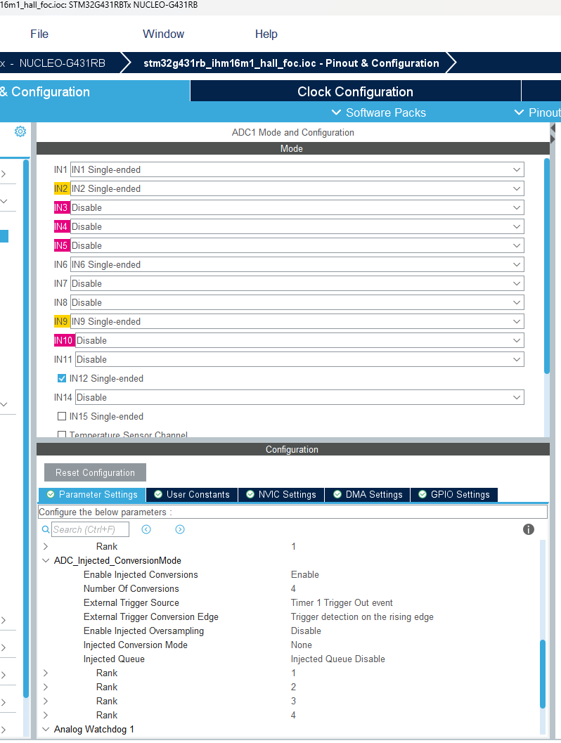
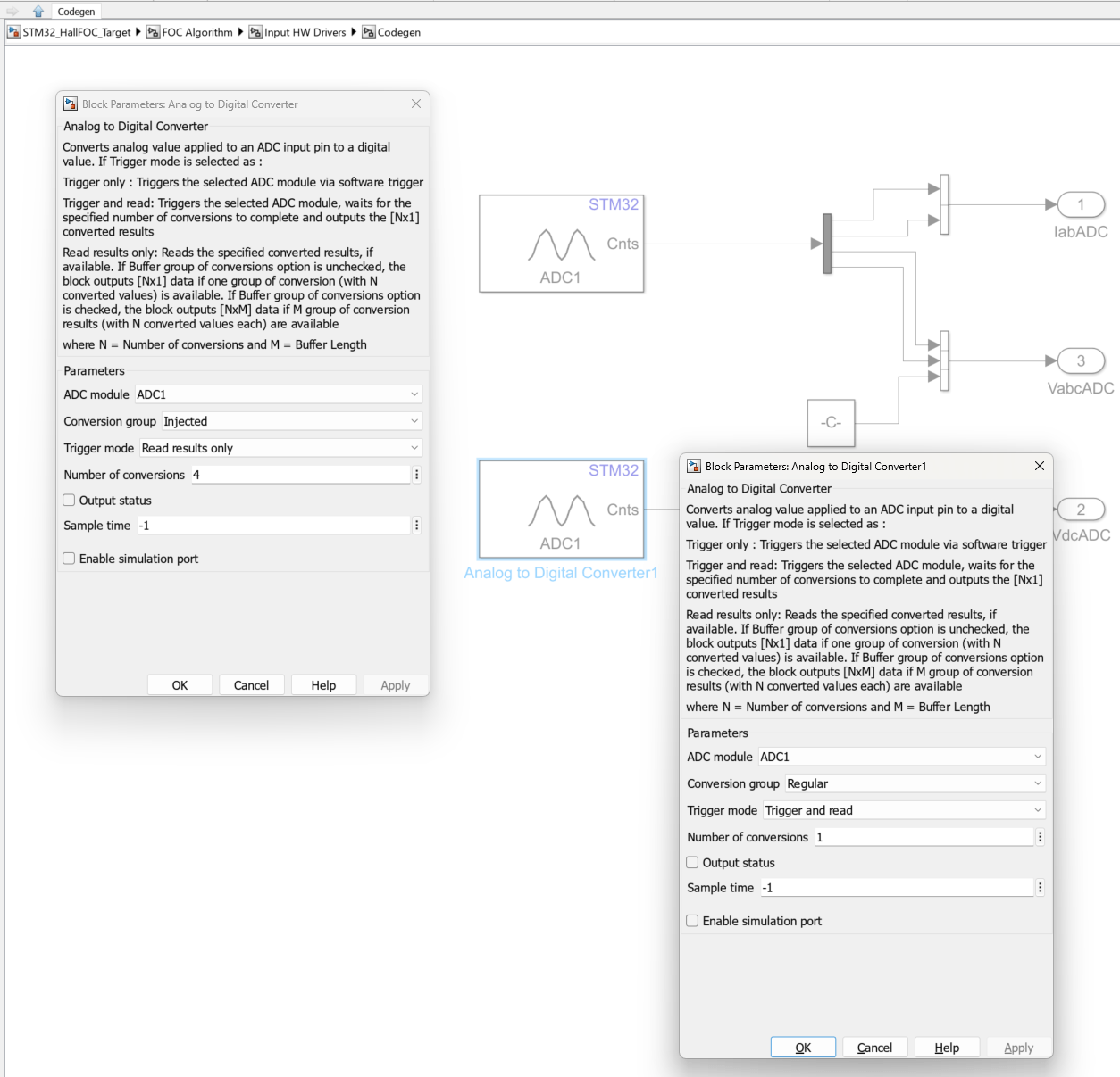
  • The ADC and PWM synchornization occurs such that ADC injected group conversions start based on Timer 1 update events.

  • The ADC is configured to read current and voltage feedback from injected conversions, and Vdc from regular conversions.

PWM Configuration

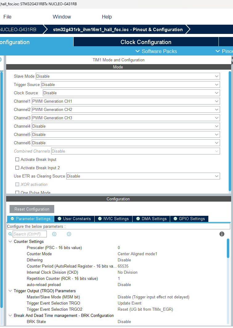
  • PWM frequency and PWM channels are configured. The Timer1 is configured to generate update events to synchronize the ADC with the PWM. This synchronization is important to read current feedback at right time.

  • The repetition counter is set to 1 to ensure update events occur once every period.

  • The counter period is updated using peripheral blocks in the model based on the value provided to the PWM_Frequency variable in STM32MotorControlData script.

Hall Sensor Interface

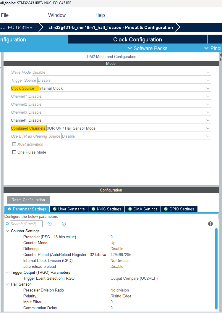
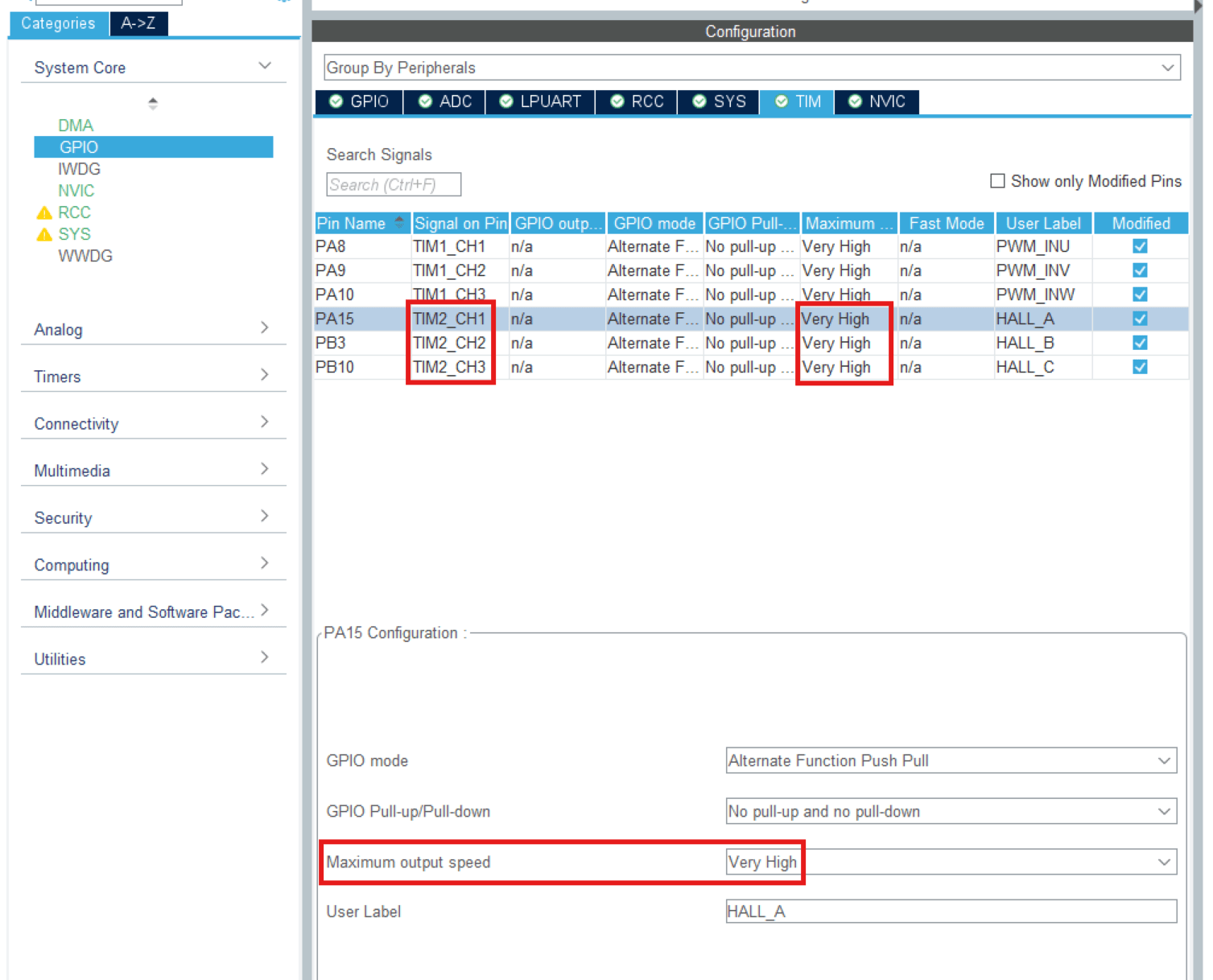
  • The Timer2 is configured in the XOR ON/Hall Sensor Mode. This timer provides us with information about the time between a transition in hall states.

  • It is ideal to use a 32-bit timer for this purpose, as a 16-bit timer may overflow before a hall transition occurs. This will result in the captured data being inaccurate. This is noticeable when operating the motor at low speeds.

  • Configure the pins used for interfacing with the GPIO pins to have a high output speed.

Serial Configuration

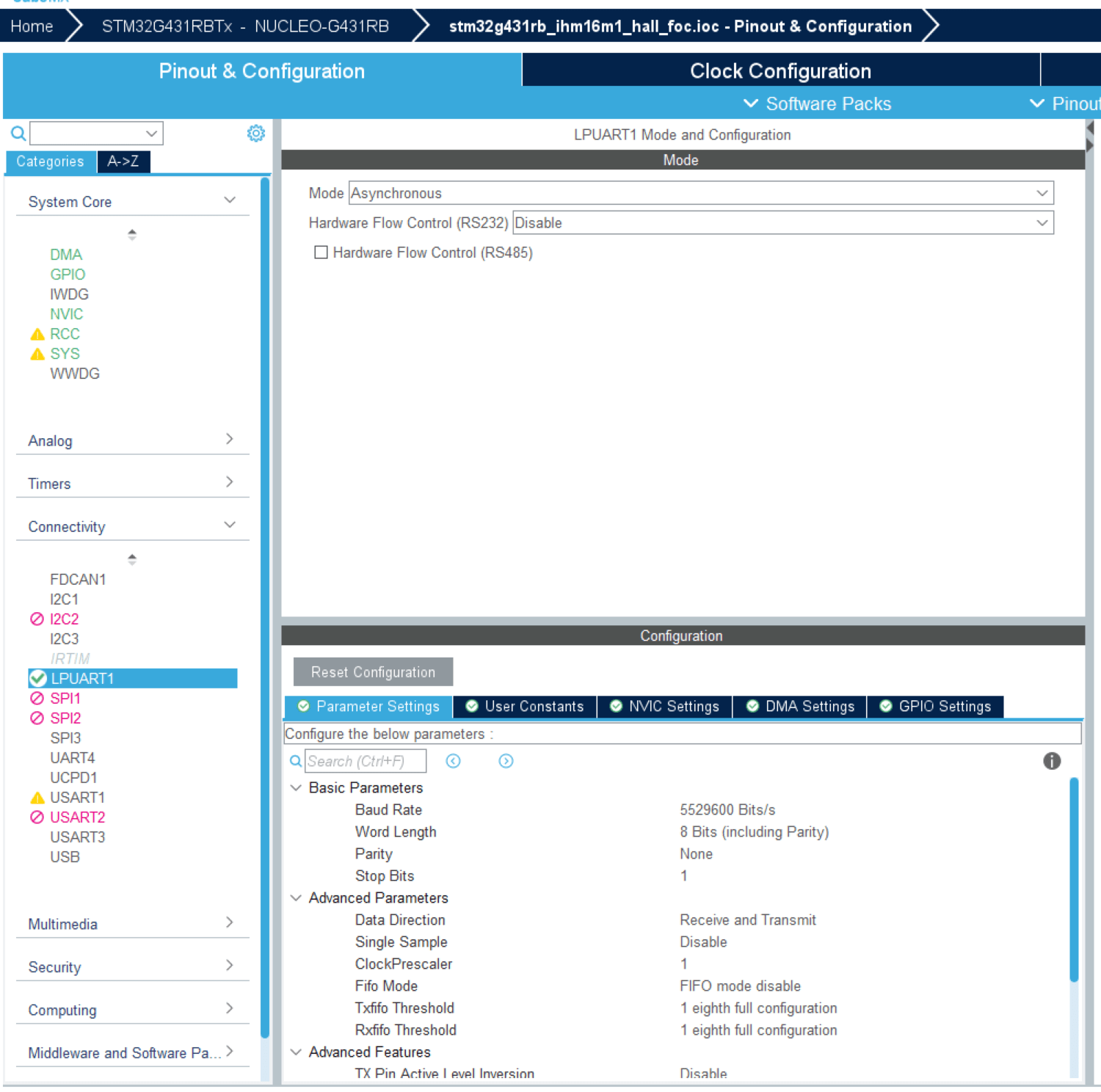
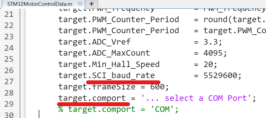
Use the LPUART module for host-target serial communication. Ensure that the baud rate set in STM32CubeMX matches the target.SCI_baud_rate variable in the STM32MotorControlData.m script.

Peripheral Block Configurations

Double-click the blocks to open the block parameter configurations. Ensure the specified parameter values are the same if you want to run this example on a different hardware board.

  • Configure Analog to Digital Converter block

The algorithm in this example uses asynchronous scheduling. The pulse width modulation (PWM) block triggers the ADC conversion. At the end of the conversion, the ADC posts an interrupt that triggers the FOC algorithm.

  • Configure PWM Output block

Select the Set the repetition counter after counter is enabled parameter to update the event when the timer counter overflows.

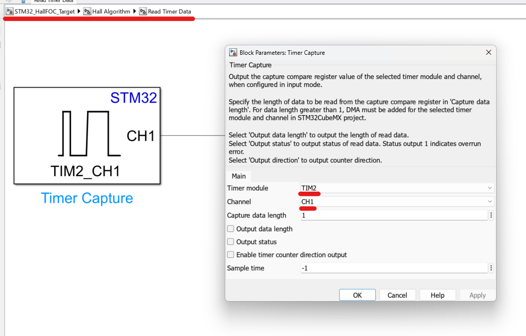
  • Configure Timer Capture Block

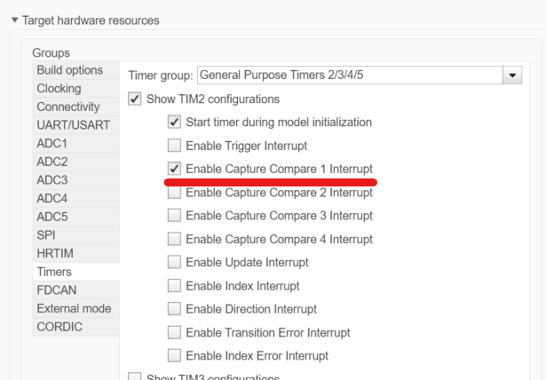
The algorithm uses Timer2 for interfacing with the Hall Sensor. A Capture Compare 1 interrupt is generated when a change in hall state occurs. The timer count at the time of transition is stored in Timer 2's Capture Compare 1 register. Make sure the capture compare 1 interrupt is enabled.

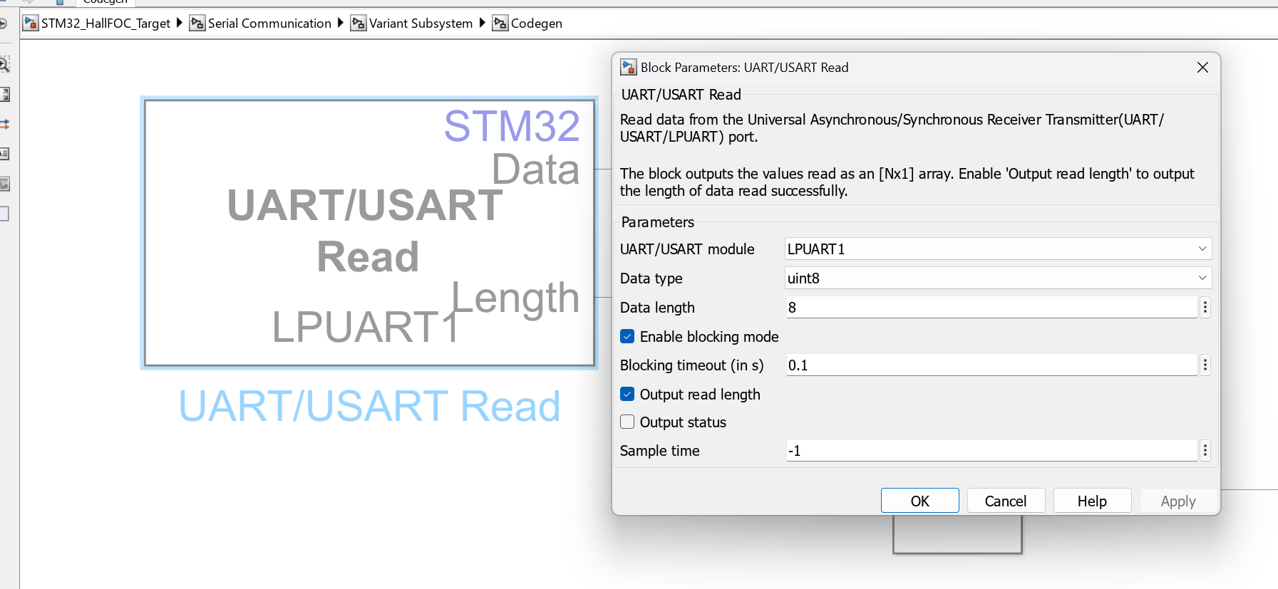
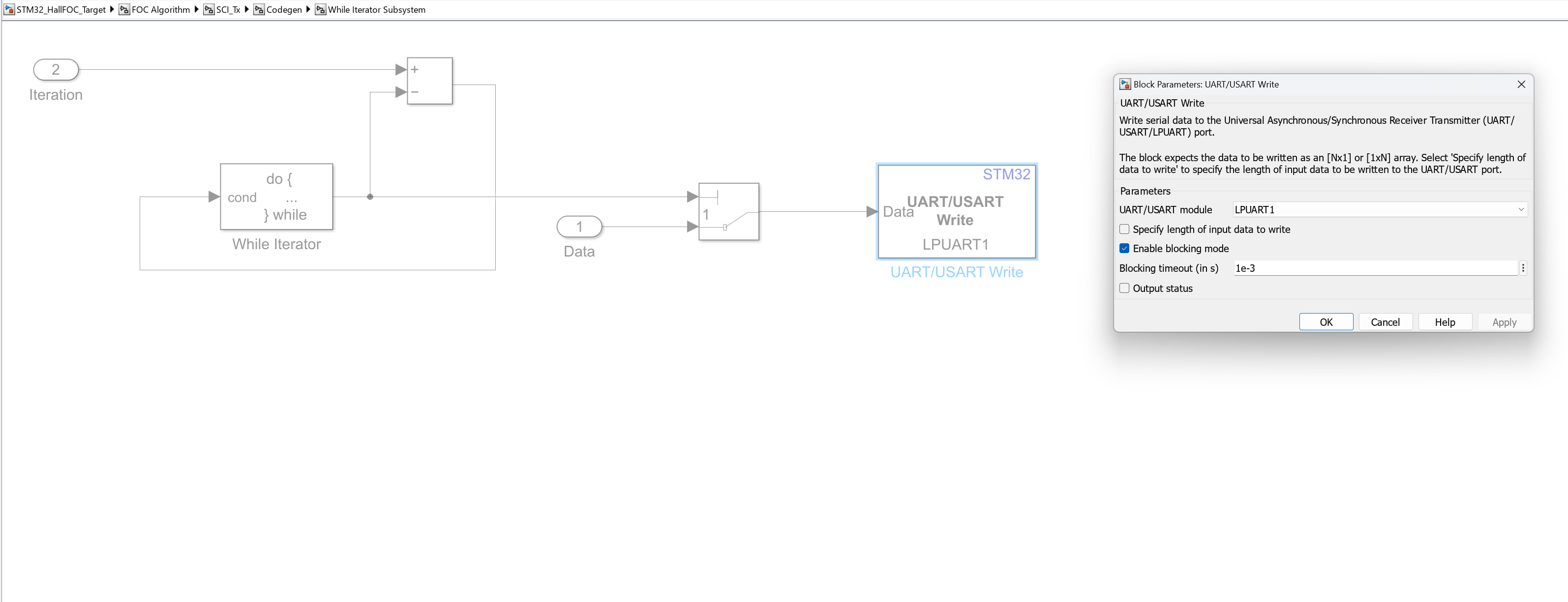
  • Configure UART/USART Read and Write Blocks

LPUART1 module is configured for communication with the host model. If you use a different USART module (such as an external FTDI for serial communication), update the USART blocks in the model accordingly.

Set the baud rate from STM32CubeMX in the STM32MotorControlData.m script. Update the COM port as well. For example:

Simulate Model

This example supports simulation. Follow these steps to simulate the model.

1. Open a STM32_HallFOC_Target included with this example.

2. To simulate the model, click Run on the Simulation tab.

3. To view and analyze the simulation results, click Data Inspector on the Simulation tab.

Generate Code, Deploy and Run on Target Hardware

This section instructs you to generate code and run the FOC algorithm on the target hardware.

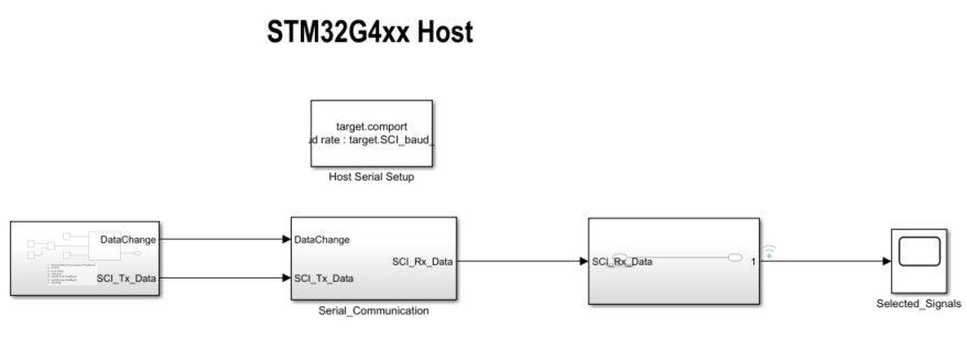
This example uses a host and a target model. The host model is a user interface to the controller hardware board. You can run the host model on the host computer. The prerequisite to use the host model is to deploy the target model to the controller hardware board. The host model uses serial communication to command the target Simulink® model and run the motor in a closed-loop control.

Generate Code and Run Model on Target Hardware

  1. Simulate the model and observe the simulation results.

  2. Complete the hardware connections.

  3. Ensure the motor parameters and hall offset value are updated. For more information, see Hall Offset Calibration for PMSM with STM32 Processors.

  4. The model automatically calculates the Analog-to-Digital Converter (ADC) or current offset values. To disable this functionality (enabled by default), update the value to 0 in the inverter.ADCOffsetCalibEnable variable in the model initialization script. Alternatively, you can compute the ADC offset values and update it manually in the model initialization scripts. For instructions, see Open-Loop Control of 3-Phase AC Motors Using STM32 Processor Based Boards.

  5. Open the target model and select the desired inverter board.

  6. Click Build, Deploy & Start on the Hardware tab to deploy the model to the hardware.

  7. In the target model, click the host model button to open the host model.

For details about the serial communication between the host and target models, see Host-Target Communication.

8. In the model initialization script associated with the target model, specify the communication port using the variable target.comport. The example uses this variable to update the Port parameter of the Host Serial Setup, Host Serial Receive, and Host Serial Transmit blocks available in the host model.

9. Update the Reference Speed value in the host model.

10. Click Run on the Simulation tab to run the host model.

11. Change the position of the Start / Stop Motor switch to On, to start running the motor.

NOTE: When you run this example on the hardware at a low Reference Speed, due to a known issue, the PMSM may not follow the low Reference Speed.

12. Observe the debug signals from the RX subsystem, in the Time Scope of host model.

More About: