Signal Monitoring and Parameter Tuning Over XCP-based CAN Interface Using STM32 Processors
This example shows how to monitor signals and tune parameters of a Simulink® model on STMicroelectronics® STM32 processor based board using XCP-based CAN Interface.
Required Hardware
Any STMicroelectronics® STM32 processor based with CAN module. This example uses
STMicroelectronics NUCLEO-F429ZI board.Any CAN network interface (for example CANcaseXL, VN1610)
You can try the same example on other supported STM32-based boards by modifying the configuration parameters and IOC file.
Model
Open the stm32_xcp_can_ext.slx pre-configured model.

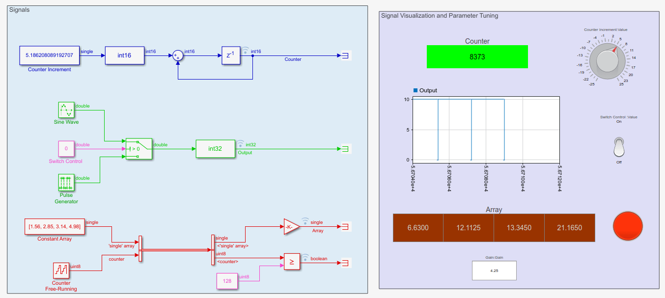
In this example, multiple signals of different data types such as int36, int32, single are selected for logging. The visualization section on the right-hand side contains Dashboard Scope and Dashboard Display blocks which shows the values of different signals that are being logged.
Different parameters in the source blocks are tunable. Dashboard Knob, Toggle Switch, and Edit boxes can also be used to tune the parameters.
Configuring the Model
In this task, you will configure a Simulink® model and enable Simulink as host interface.
Note: These steps are not required in the pre-configured model. Perform these steps if you have changed the hardware or not using the pre-configured model.
1. Open the model.
2. Go to Modeling > Model Settings to open the Configuration Parameters dialog box.
3. Open the Hardware Implementation pane, and select the required STM32 based board from the list in Hardware board parameter.
4. Expand Target hardware resources for that board.
5. Go to External mode tab and choose CAN as the Communication interface.
6. Select Simulink as the Host interface.
Select Verbose option to view the External Mode execution progress and updates in the Diagnostic Viewer or in the MATLAB Command Window.
Select Set logging buffer size automatically option to set the optimal buffer size for logging data.

7. Configure the CAN module on the target.

Select the CAN module to use with external mode, if the target supports multiple CAN and FDCAN modules.
The displayed baudrate is the one specified in the IOC file.
Set the Read source to FIFO0 and CAN Vendor to Vector.
Select Extended CAN ID option, if you want to use extended ID.
Enter the values for CAN ID command and CAN ID response.
8. Click Apply and OK. Initiate Monitor and Tune Action for the Model
STM32CubeMX Configurations
1. Open the Modeling tab and press CTRL+E to open the Configuration Parameters dialog box. Go to Hardware Implementation > Target Hardware Resources > Build options.
2. Click Browse. Browse for the stm32f4xx_xcp_can_ext.ioc file and click OK
3. Click launch to open the IOC file.
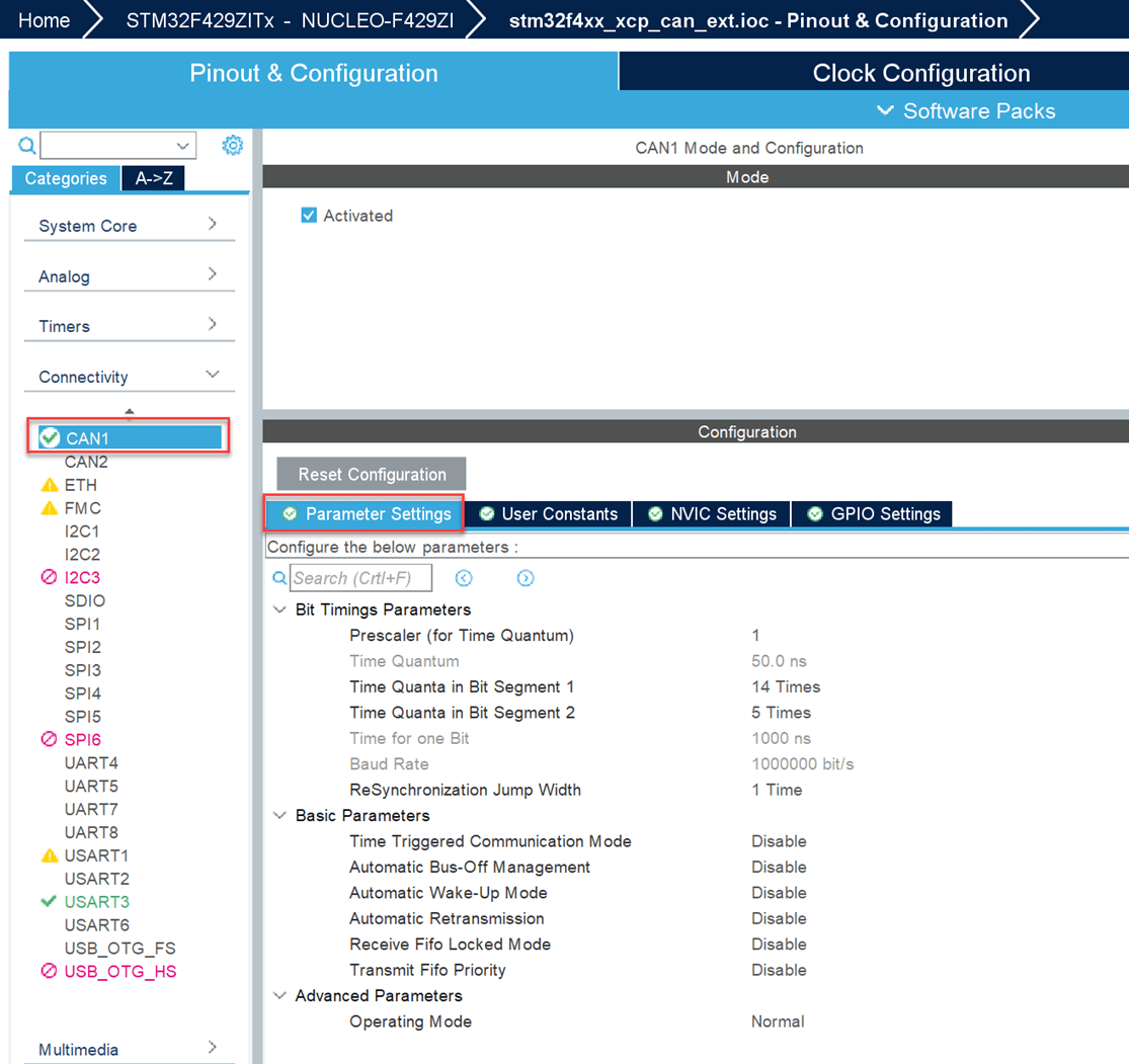
4 In the IOC file, Go to Pinout & Configuration > Connectivity > CAN and configure the parameters as shown.

Initiate Monitor and Tune Action for Model
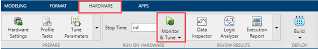
On the Hardware tab of the Simulink toolstrip, click Monitor & Tune to monitor signals and tune parameters.
Related Topics