Main Content

Set Up External Mode Connectivity Between Simulink and Target Hardware

For external mode simulations, you can use the target Package to provide connectivity between Simulink® and your target hardware.

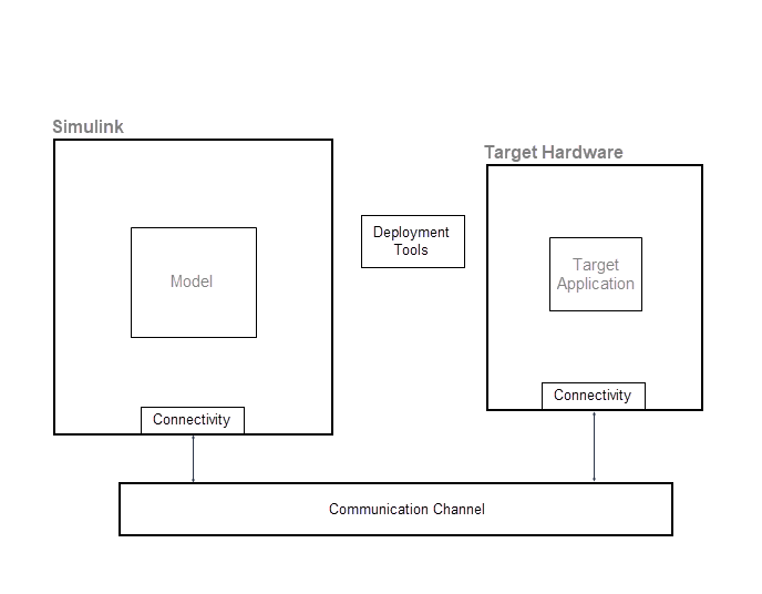
This diagram gives an overview of the components of an external mode simulation.

The target package provides classes for the implementation of components. This table lists the main classes.

ComponentClassPurpose
Target hardwaretarget.BoardProvide MATLAB® with a description of target hardware.
Deployment tools target.SystemCommandExecutionTool

You can use the classes to:

  • Capture system commands for running the target application from your development computer.

  • Describe the execution service implementation for the target application.

  • Provide the MATLAB service interface for the tool that manages the target application execution.

To provide Monitor & Tune, Deploy, Connect, and Start functionality, the Run on Custom Hardware app requires the use of target.ExecutionTool.

target.ExecutionService
target.ExecutionTool
Connectivity target.ExternalModeProvide communication protocol for data transfer between Simulink and target hardware.
target.CommunicationInterfaceProvide target hardware with details of the communication channel and the rtiostream API implementation.
target.TargetConnectionProvide details about connecting development computer to target hardware.

Customise Connectivity for XCP External Mode Simulations

For code that is generated by using ERT (ert.tlc) and GRT (grt.tlc) system target files, you can run external mode simulations that use the XCP communication protocol:

  • On your development computer.

  • On other target hardware by using support packages.

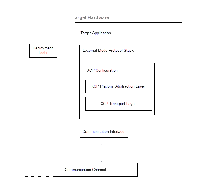
If your system target file for custom target hardware is derived from the ERT or GRT system target files, use classes from the target Package to customise connectivity. For example, target.ExternalMode and target.CommunicationInterface.

This example shows how you can customise connectivity for XCP-based external mode simulations. To set up connectivity between Simulink and the target hardware:

  1.  Create board description

  2.  Choose deployment tool

  3.  Using target.ExecutionTool

  4.  Using target.SystemCommandExecutionTool

  5.  Create communication interface for target hardware

  6.  Specify communication protocol stack

  7.  Create connection between Simulink and target hardware

  8.  Make board and connection objects persist across MATLAB sessions

  9.  Select board for model

  10.  Select connection between Simulink and target hardware

Customize Connectivity for TCP/IP or Serial External Mode Simulations

For TCP/IP or serial external mode simulations, you can customize connectivity through a workflow that:

  • Implements transport and communication protocols.

  • Specifies the execution tool for the target application by using the target Package package.

To set up connectivity between Simulink and the target hardware, use the workflow described in Customise Connectivity for XCP External Mode Simulations with these differences:

Execution Tool Template

This section provides a pseudocode example for a target.ExecutionTool service interface. The tool starts and tracks an application on the target hardware.

classdef MyExecutionTool < target.ExecutionTool

  methods        
    function errFlag = startApplication(this)
      % Call "customDownloadTool" to download the application.
      [status, result] = ...
       system(sprintf('customDownloadTool %s', this.Application));
      if status == 0
        errFlag = false;                
      else
        disp(result);
        errFlag = true;
      end
    end

    function errFlag = stopApplication(~)
      % Add code here to stop the application, if possible.
      errFlag = false;
    end

    function [status, errFlag] = getApplicationStatus(~)
      % Add code here to return the application status, if known.
      status = target.ApplicationStatus.Unknown;
      errFlag = false;
    end
  end
end

See Also

Related Topics

External Websites