Create Fault Tree Gates
R2026bIn fault tree documents, gates calculate failure properties from input events and gates. After calculating the failure properties, they propagate the calculated properties up to the top-level gate. Failure properties include the probability, also known as unavailability, and the failure frequency. The type of gate determines the calculations that the gate performs.
Gates can use events and other gates as inputs. You can connect gates and events directly to the input of a gate, or use transfer gates to use another gate in the fault tree document as an input.
Add Gate to Fault Tree
To add a gate to a fault tree:
Open the Safety Analysis Manager. In MATLAB® or Simulink®, in the Apps tab, click Safety Analysis Manager.
Create or open a fault tree document.
To create a new document, click New > Fault Tree Document.
To open an existing document, click Open and select the document.
Select a gate. New fault tree documents contain one fault tree, which contains only one top-level gate.
In the Tree section, click Or and select the gate type.
You can add these gate types:
| Gate Type Symbol | Gate Type | Description |
|---|---|---|
|
| OR | Calculates the union of the input unavailabilities and frequencies. |
|
| AND | Calculates the intersection of the input unavailabilities and frequencies. |
|
| NOT | Calculates the probability that an input does not occur. For example,
if the input probability is 1, the not gate returns a
probability of 0. You can specify only one input to
this gate. |
|
| Exclusive OR | Calculates the probability that only one event occurs. You can specify only two inputs to this gate. |
|
| Voting Algorithm | Calculates the probability that the specified number of the inputs or more occurs. |
Copy Gates
When you copy and paste gates, the new gate retains the properties of the original gate, but has a new name. For more information, see Copy Fault Tree Artifacts.
Define Gate Properties
To view the properties of a gate, click the gate. The properties appear in the Properties pane.
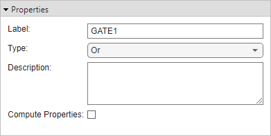
You can also change the gate label or enter a description by using the Label and Description properties, respectively. You can change the type of gate by using the Type property. For voting gates, you can also specify the number of inputs by setting k to a positive integer.
By default, the Safety Analysis Manager calculates the failure properties only for the top-level gate and events. To calculate the failure properties for the selected gate, select Compute Properties. For more information about the failure properties, see Define Event Properties and Quantitative Results.
View All Gates in Fault Tree Document
You can view all of the gates in the fault tree document
and their properties in the Artifacts pane. To open the pane, click
Artifacts at the bottom of the Safety Analysis
Manager. To view the gates in the fault tree, set the drop-down list in the
top-left corner to Gates.
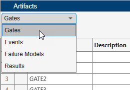
To view the location of the gate in your fault tree, select the gate and click the Highlight gate in tree button .
To filter the gates, enter a term in the Search box. You can use the
drop-down list to filter the results based on the specified property. For checkbox
columns, enter true or false to filter the
results.
You can select multiple gates by pressing Shift and clicking the artifacts. Selecting one gate displays the properties in the Properties pane.
By default, the Artifacts pane lists the gates by order of their creation. To sort the gates alphabetically, point to the right side of a column and click. You can sort alphabetically in ascending or descending order.
Create Transfer Gates
Transfer gates can use another gate in the fault tree as the source of their input data. Use transfer gates when you cannot connect a gate or an event directly to a gate or if you want to connect separate fault trees to other fault trees.
To add a transfer gate to a selected gate:
In a fault tree, select a gate.
In the toolstrip, in the Tree section, click Transfer In.
The transfer gate icon indicates a transfer gate. When you select the gate, the Properties pane displays the properties.
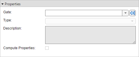
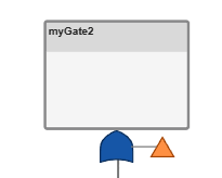
To define the source of the input data, set the Gate property. You can select gates in the same or a different fault tree. The transfer gate icon indicates that a gate outputs its data to a transfer gate.
Note
If a transfer gate creates a circular logic loop or logical redundancy, the Safety Analysis Manager displays an error.
Convert Gates and Attached Artifacts to Standalone Trees
You can convert a gate and its attached artifacts into a separate fault tree by converting the gate to a transfer gate. To convert a gate into a transfer gate, right-click the gate and click Convert to tree. The fault tree replaces the gate with a transfer gate.
View Transfer Gate Data Sources
A gate can transfer data to multiple transfer gates. To view the transfer gates that use the gate as a data source:
Select the gate.
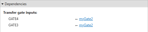
In the Properties pane, expand the Dependencies section.