Generate IP Core with AXI4-Stream Interface for Generic Microchip Platforms
To generate IP cores with AXI4-Stream interfaces for generic Microchip platforms, you start by designing a Simulink® model that models the AXI4-Stream interfaces. Then you generate the IP core, integrate it into your Libero® SoC project, and deploy the design to a Microchip platform.
Prepare Model That Uses AXI4-Stream Interface
Create models that contain AXI4-Stream interfaces when you want to model applications that require high-speed data transfer, such as digital signal processing (DSP) or image processing algorithms. For more information on how to design model for AXI4-Stream interface, see Model Design for AXI4-Stream Interface Generation.
To open the example model, enter these command in the MATLAB® Command Window:
openExample("hdlcoder/AXI4StreamInterfaceInZynqWorkflowExample")
open_system("hdlcoder_sfir_fixed_stream.slx")
set_param("hdlcoder_sfir_fixed_stream","SimulationCommand","Update")
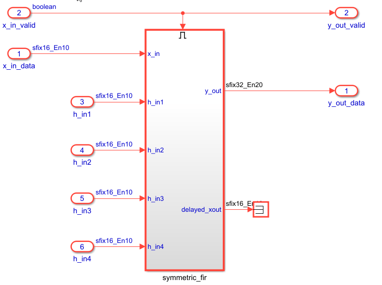
The hdlcoder_sfir_fixed_stream model contains a design under test
(DUT) subsystem represents the hardware subsystems that target the FPGA fabric. This model
uses the simplified streaming protocol modeling pattern. The
symmetric_fir subsystem is an enabled subsystem. The input control
signal, x_in_valid manages the enable port of the subsystem and also
drives the output control signal, y_out_valid. The data signals,
x_in_data and y_out_data, constitute the data path
of the filter. For more information, see Generate IP Core with an AXI4-Stream Interface.
Generate HDL IP Core for Generic Microchip Platforms
To generate the HDL code and IP core for a generic Microchip platform, follow these steps:
Set the synthesis tool to Microchip Libero SoC by using the
hdlsetuptoolpathfunction.Use your own Libero SoC installation path when executing the command. For more information, seehdlsetuptoolpath("ToolName","Microchip Libero SoC","ToolPath",liberopath);
hdlsetuptoolpath.In the Simulink Apps gallery, select HDL Coder app. In the top model, click the
DUTsubsystem. In the HDL Code tab, ensure that Code for is set toDUT. Click Workflow Advisor to open the HDL Workflow Advisor.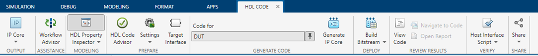
In the 1.1. Set Target > Set Target Device and Synthesis Tool task, set Target workflow to
IP Core
              Generation
and Target platform toGeneric Microchip Platform. Click Run This Task.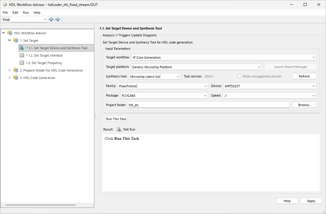
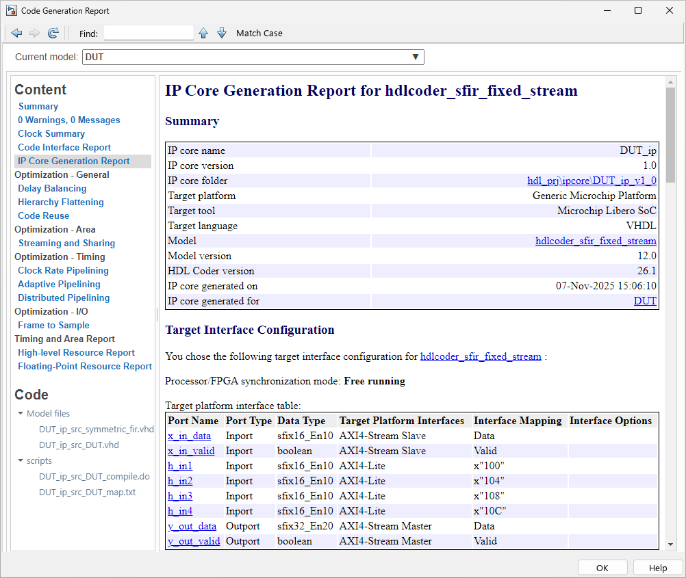
In the 1.2 Set Target Interface task, in the Target platform interface table, set the target platform interfaces for the input and output ports by using the Target Platform Interfaces column. For the input ports,
x_in_dataandx_in_valid, set Target Platform Interfaces toAXI4-Stream Slave. Map the output ports,y_out_dataandy_out_valid, toAXI4-Stream Master. For the control parameter ports, such ash_in1, set the interfaces toAXI4-Lite. Click Apply and then Run This Task.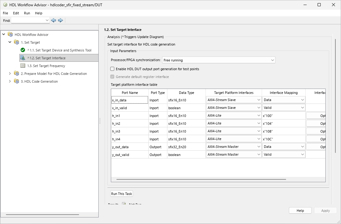
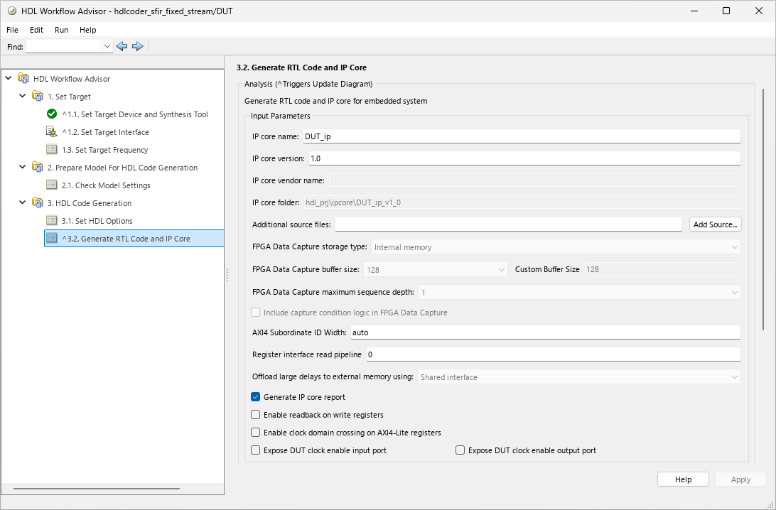
In the 3. HDL Code Generation > 3.2 Generate RTL Code and IP Core task, select Generate IP core report to generate IP core generation report. Click Run This Task to generate the HDL code and IP core for the model.
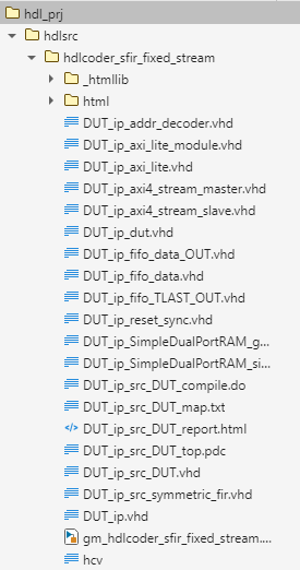
The HDL Workflow Advisor generates IP core files in the IP core folder, including the HTML files. The folder contains the HDL IP core for the DUT subsystem.
To view the IP core generation report, click the IP Core Generation Report HTML link in the log section.
You can integrate the generated IP core to your reference design by using a Libero SoC project. For more information on how to insert an HDL IP core into a Microchip Libero SoC project, see Generate Board-Independent HDL IP Core for Microchip Platforms.