Define Custom Board and Reference Design for Sobel Edge Detection Algorithm on Microchip Platform
This example shows how to create a reference design for a Sobel edge detection algorithm on a Microchip platform. You use this reference design to target a Microchip PolarFire® SoC (PFSoC) video kit. You can also follow the steps in this example to define custom board and reference design for other Microchip platforms.
Requirements
To run this example, you must have:
Microchip Libero® SoC Design Suite — For more information on the supported version of this design suite, see HDL Language Support and Supported Third-Party Tools and Hardware.
Microchip PolarFire SoC Video Kit — To learn more about PolarFire SoC Video Kit, see PFSOC Video Kit Reference Manual on the Microchip website.
HDL Coder™ Support Package for Microchip FPGA and SoC Devices — See Download and Install HDL Coder Support Package for Microchip FPGA and SoC Devices.
USB COM Port Device Drivers — Connect the shared UART/JTAG USB port on the PolarFire SoC Video Kit to your computer.
Create Custom Reference Design by Using Microchip Libero SoC
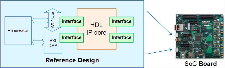
A reference design captures the complete structure of an SoC design and define the different components and their connections. Reference designs integrate with IP cores, which you can use to program the SoC board. This figure shows the relationship between a reference design, an HDL IP core, and an SoC board.
Set up the tool path to the Microchip Libero SoC by using the hdlsetuptoolpath function. Specify ToolName as Microchip Libero SoC and ToolPath as your installed Libero executable path.
hdlsetuptoolpath('ToolName', 'Microchip Libero SoC', 'ToolPath', 'liberopath');
To create and export a reference design by using the Microchip Libero SoC tool environment, follow these steps:
1.In the Microchip Libero SoC tool, create a RTL project. Use these board settings for PolarFire SoC board:
Family:
PolarFireSoCDie:
MPFS250TSPackage:
FCG1152Speed:
-1Core Voltage:
AllRange:
All
2. In the Design Flow tab, Click Create SmartDesign and specify the design name as Libero_sd.
3. Add the HDMI_TX, HDMI_RX , PF_XCVR_ERM, CORE_FIFO, OSC_C0, FCCC_C0 and COREAXI4INTERCONNECT_C0 IPs to the smart design and configure these IPs with default settings. Connect these IPs such that the data received at the HDMI_RX port transmits to the FPGA. The PFSoC fabric processes the data and sends it to the HDMI_TX port. This design employs FIFO to ensure that output transmits properly without data loss.
4. To export the block design as a TCL script with the name design1_led.tcl, select Project > Export Script File.
The exported TCL script constitutes the custom reference design. You use this reference design in the HDL Workflow Advisor to recreate the block design and integrate the HDL IP core with the block design in a Libero project.
Register PolarFire SoC Video Kit in HDL Workflow Advisor
To register the PFSoC Video Kit in the HDL Workflow Advisor, follow these steps:
1. Create a board registration file with the name hdlcoder_board_customization.m and add it to the MATLAB® path. A board registration file contains a list of board plugins. A board plugin is a MATLAB package folder that contains a board definition file and all the reference design plugins associated with the board.
You can use this code for the hdlcoder_board_customization.m file. The hdlcoder_board_customization.m file contains PFSoC registration board plugin to register the PFSoC Video Kit in HDL Workflow Advisor. The function finds any registration file with the specified name on the MATLAB path and returns a cell array with the locations of the board plugins. The board plugin must be a package folder that is accessible from your MATLAB path and must contain a board definition file.
function r = hdlcoder_board_customization
% Board plugin registration file

r = { ...
      'PolarFireSoCRegistration.plugin_board', ...
     };
end
2. Create the board definition file. A board definition file contains information about the SoC board. Create a PFSoC video kit board definition file named plugin_board.m that resides inside the board plugin PolarFireSoCRegistration. For more information about the FPGA I/O pin locations and standards, see the PFSOC video kit constraints file on the Microchip website.
The property BoardName defines the name of the PFSOC video kit in the HDL Workflow Advisor.
function hB = plugin_board()
% Board definition

%   Copyright 2025 The MathWorks, Inc.

% Construct board object
hB = hdlcoder.Board;

hB.BoardName    = 'Microchip PolarFire SoC Video Kit';

% FPGA device information
hB.FPGAVendor   = 'Microchip';
hB.FPGAFamily   = 'PolarFireSoC';
hB.FPGADevice   = 'MPFS250TS';
hB.FPGAPackage  = 'FCG1152';
hB.FPGASpeed    = '-1';

% Tool information
hB.SupportedTool = {'Microchip Libero SoC'};

% FPGA JTAG chain position
hB.JTAGChainPosition = 2;

%% Add interfaces
% Standard "External Port" interface
hB.addExternalPortInterface( ...
    'IOPadConstraint', {'IOSTANDARD = LVCMOS33'});

% Custom board external I/O interface
hB.addExternalIOInterface( ...
    'InterfaceID',    'LEDs General Purpose', ...
    'InterfaceType',  'OUT', ...
    'PortName',       'LEDs', ...
    'PortWidth',      4, ...
    'FPGAPin',        {'AE27', 'AE22', 'AP28', 'AP29'}, ...
    'IOPadConstraint', {'IOSTANDARD = LVCMOS33'});

hB.addExternalIOInterface( ...
    'InterfaceID',    'DIP Switches', ...
    'InterfaceType',  'IN', ...
    'PortName',       'DIPSwitched', ...
    'PortWidth',      4, ...
    'FPGAPin',        {'AN28', 'AM28', 'AN26', 'AN27'}, ...
    'IOPadConstraint', {'IOSTANDARD = LVCMOS25'});

hB.addExternalIOInterface( ...
     'InterfaceID',    'Push Buttons', ...
     'InterfaceType',  'IN', ...
     'PortName',       'PushButtons', ...
     'PortWidth',      2, ...
     'FPGAPin',        {'AJ21', 'AL24'}, ...
     'IOPadConstraint', {'IOSTANDARD = LVCMOS25'});
Register Custom Reference Design in HDL Workflow Advisor
To register the custom reference design in the HDL Workflow Advisor, follow these steps:
1. Create a reference design registration file named hdlcoder_ref_design_customization.m that contains a list of the reference design plugins associated with an SoC board. A reference design plugin is a MATLAB package folder that contains the reference design definition file and all the files associated with the SoC design project. A reference design registration file must also contain the name of the associated board.
You can use this code for the hdlcoder_ref_design_customization.m file. This code describes the contents of the PFSoc Video Kit reference design registration file and contains the reference design plugin PolarFireSocRegistration.Libero_2024_1. To use this code for a different Microchip Libero SoC tool, change this plugin to the PFSoC Video Kit associated with that SoC tool. The registration file finds files with the specified name inside a board plugin folder or on the MATLAB path. The function returns a cell array that contains the location of the reference design plugins and a character vector that contains the associated board name. The reference design plugin must be a package folder that is accessible from the MATLAB path and must contain a reference design definition file.
function [rd, boardName] = hdlcoder_ref_design_customization

%   Copyright 2025 The MathWorks, Inc.

rd = { ...
    'PolarFireSoCRegistration.Libero_2024_1.plugin_rd',...
    };

boardName = 'Microchip PolarFire SoC Video Kit';

end
2. Create the reference design definition file. A reference design definition file defines the interfaces between the custom reference design and the HDL IP core that you generate. Create a PFSoC Video Kit reference design definition file named plugin_rd.m to associate the file with the Microchip PolarFire SoC Video Kit board that resides inside the reference design plugin PolarFireSoCRegistration.Libero_2024_1. The ReferenceDesignName property defines the name of the reference design as Default system with AXI4 Stream interface (requires HDMI) in the HDL Workflow Advisor.
function hRD = plugin_rd()
% Reference design definition

%   Copyright 2025 The MathWorks, Inc.

% Construct reference design object
hRD = hdlcoder.ReferenceDesign('SynthesisTool', 'Microchip Libero SoC');

hRD.ReferenceDesignName = 'Default system with AXI4 Stream interface (requires HDMI)';
hRD.BoardName = 'Microchip PolarFire SoC Video Kit';

% Tool information
hRD.SupportedToolVersion = {'2024.1'};

% Add custom design files
% add custom Libero  design
hRD.addCustomLiberoDesign( ...
    'CustomBlockDesignTcl', 'design1_led.tcl');

% Add constraint files
hRD.CustomConstraints = {'io_constraints.pdc','fp_constraints.pdc','timing_user_constraints.sdc','libero_sd_derived_constraints.sdc'};
% %
% other custom files/folders
hRD.CustomFiles = {'HDMI_TX_Initiator_IF.v'};
% %
% %% Add interfaces
% add clock interface
hRD.addClockInterface( ...
    'ClockConnection',     'PF_XCVR_ERM_C0_0/LANE1_TX_CLK_R', ...
    'ResetConnection',     'PFSOC_INIT_MONITOR_C0_0/DEVICE_INIT_DONE',...
    'DefaultFrequencyMHz', 50,...
    'MinFrequencyMHz',     5,...
    'MaxFrequencyMHz',     500,...
    'ClockModuleInstance', 'PF_XCVR_ERM_C0_0',...
    'ClockModuleComponent','PF_XCVR_ERM_C0',...
    'ClockNumber',         1);

% add AXI4-Stream interface
hRD.addAXI4StreamInterface( ...
    ... % Hardware (FPGA) properties
    'MasterChannelEnable',              true, ...
    'SlaveChannelEnable',               true, ...
    'MasterChannelConnection',          'HDMI_TX_C0_0/AXI4Stream_Target_IF', ...
    'SlaveChannelConnection',           'HDMI_TX_Initiator_IF_0/HDMI_AXI_Stream', ...
    'MasterChannelDataWidth',           32, ...
    'SlaveChannelDataWidth',            32);

% Disable Processing System for now even though this is SoC Based board
hRD.HasProcessingSystem = false;
A reference design plugin must also contain the SoC design project files. The PFSoC Video Kit reference design plugin folder PolarFireSoCRegistration.Libero_2024_1 must contain the TCL script design1_led.tcl that you exported from the Microchip Libero project. The PFSoC Video Kit reference design definition file plugin_rd.m identifies the SoC design project file by using the addCustomLiberoDesign function.
The reference design definition file plugin_rd.m also defines the interface connections between the custom reference design and the HDL IP core by using the addClockInterface and addAXI4StreamInterface functions.
Generate HDL IP Core for PolarFire SoC Video Kit
Use the custom board and reference design registration system to generate an HDL IP core that blinks LEDs on the PFSOC video kit.
1. Add the PFSoC Video Kit registration files to the MATLAB path using these commands:
hdlcoder_microchip_examples_root;
addpath(fullfile(hdlcoder_microchip_examples_root,'PolarFireSocVideo'));
2. Open the Sobel edge detection model named hdlcoder_sobel_video_axi4_stream.
open_system('hdlcoder_sobel_video_axi4_stream')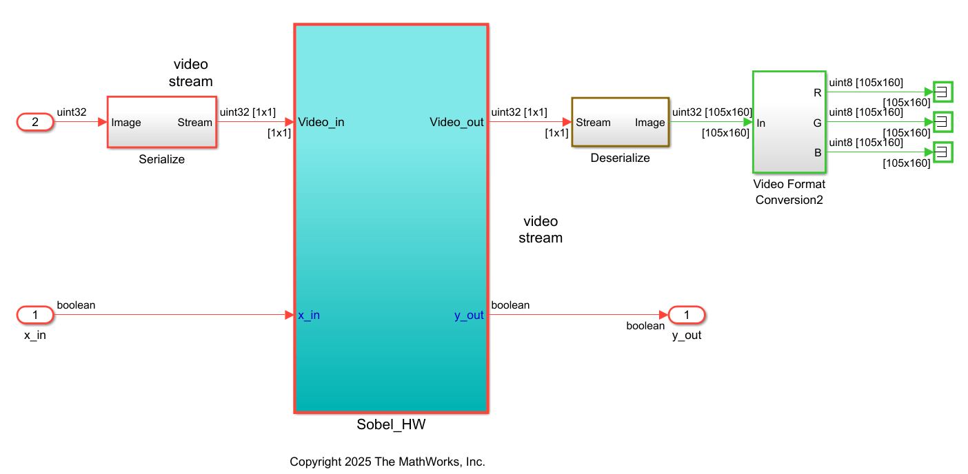
3. Launch the HDL Workflow Advisor from the hdlcoder_sobel_video_axi4_stream/Sobel_HW subsystem by right-clicking the Sobel_HW subsystem and selecting HDL Code > HDL Workflow Advisor.
4. In the Set Target > 1.1 Set Target Device and Synthesis Tool task, set Target workflow to IP Core Generation, Target platform to Microchip PolarFire SoC Video Kit, and Synthesis tool to Michrochip Libero SoC. Click Run This Task.
5. In the Set Target > 1.2 Set Target Reference Design task, set Reference design to Default system with AXI4 Stream interface (requires HDMI) and click Run This Task.
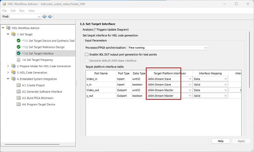
6. In the Target platform interface table in 1.3 Set Target Interface task, set the Target Platforms Interaces of Video_in and x_in input ports to AXI4-Stream Slave and Video_out and y_out output ports to AXI4-Stream Master. Click Run This Task.
7. In the 1.4 Set Target Frequency task, set Target Frequency to 50 MHz.
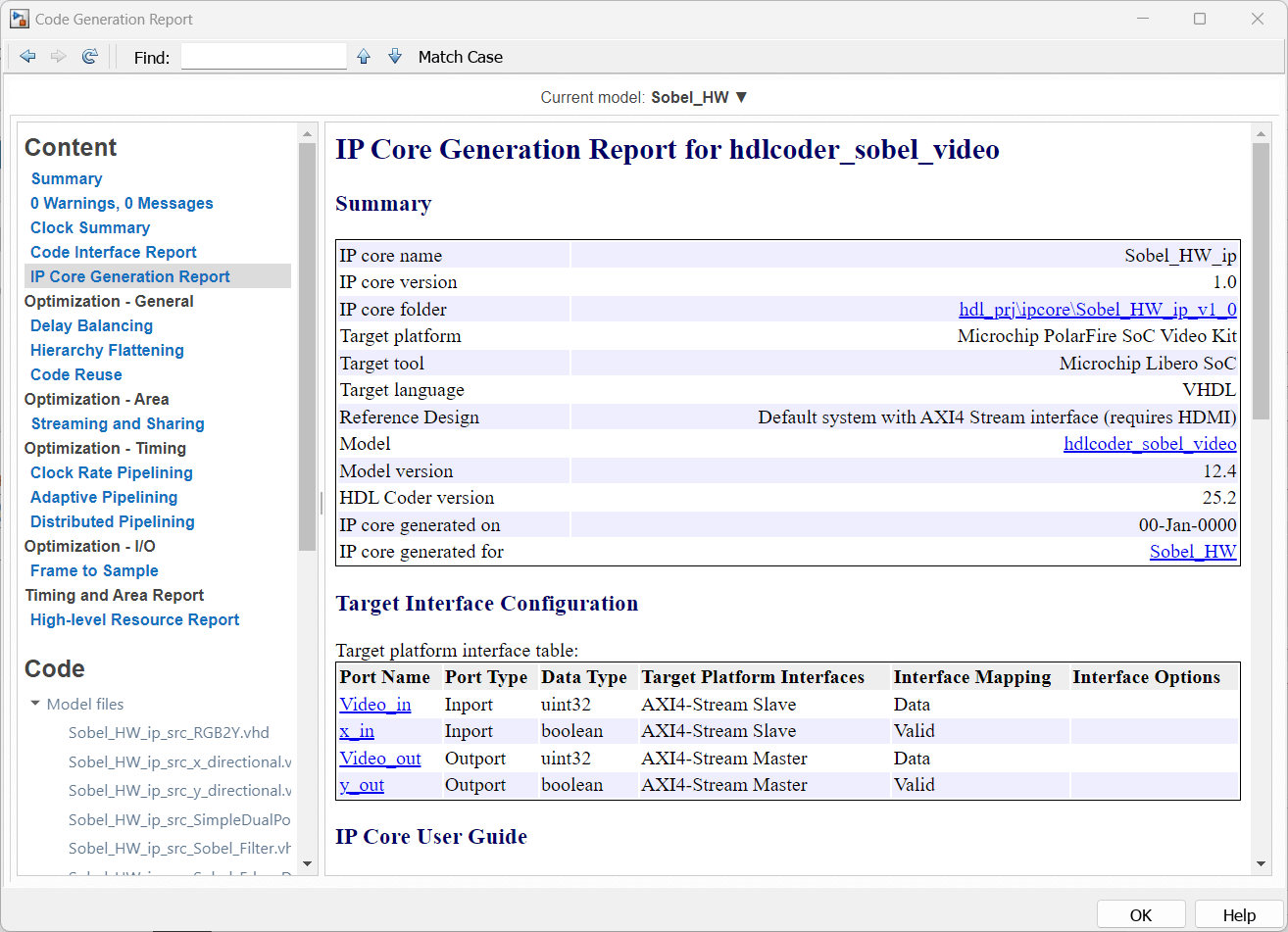
8. To generate the IP core and view the IP core generation report, right-click 3. HDL Code Generation > 3.2 Generate RTL Code and IP Core and select Run to Selected Task. After you generate the custom IP core, the IP core files are in the ipcore folder of your project folder. HDL Workflow Advisor also generates an HTML custom IP core report. The report describes the behavior and contents of the generated custom IP core.
Integrate IP Core in PolarFire SoC Video Kit Reference Design
Insert your generated IP core into the embedded system reference design, generate an FPGA bitstream, and download the bitstream to the PolarFire SoC Video Kit.
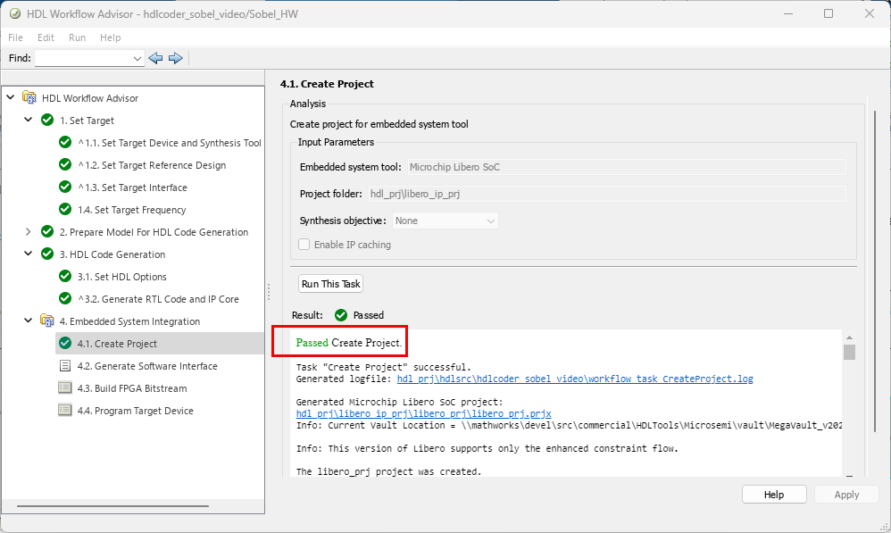
1. Create the Libero project. Select the 4. Embedded System Integration > 4.1 Create Project and click Run This Task. The HD Workflow Advisor creates a Microchip Libero project with the IP Integrator embedded design.
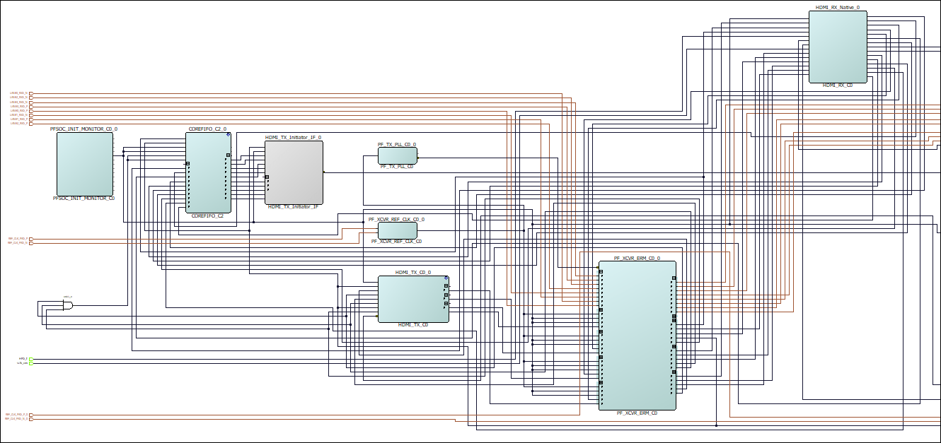
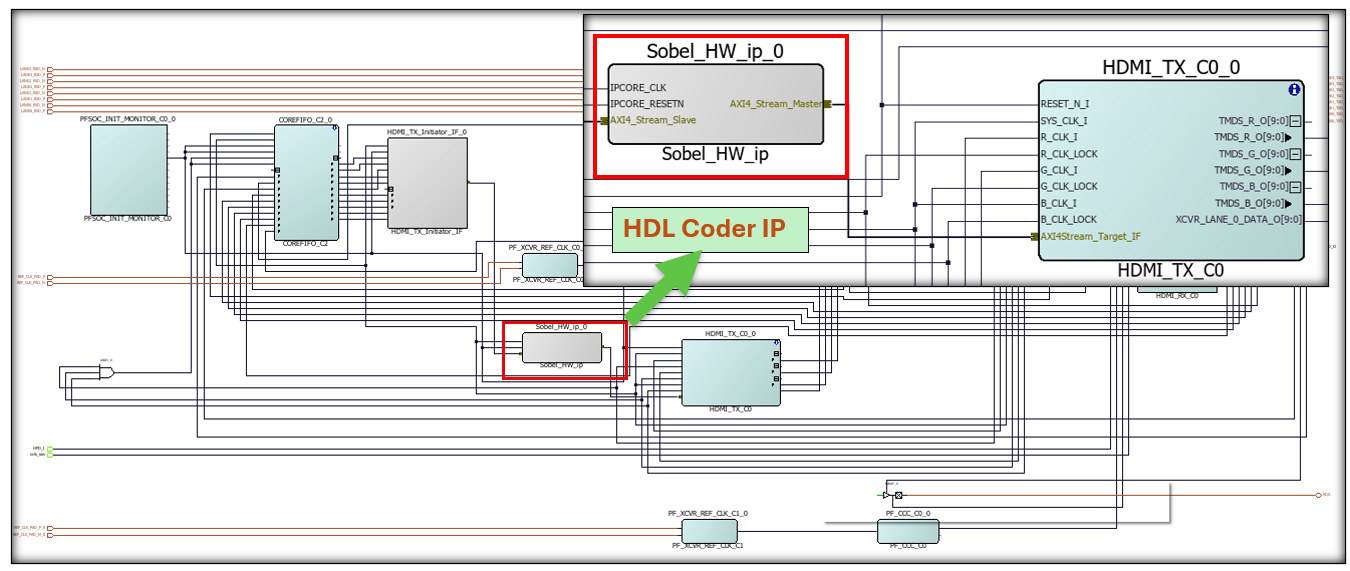
2. After the task completes, examine the Microchip Libero SoC project. This figure shows the block design of the SoC project and highlights the HDL IP core. To better understand the relationship between the reference design and the HDL IP core, you can compare this block design with the previous block design that you used to export the custom reference design.
3. Build the FPGA bitstream. Right-click the task 4.3 Build FPGA Bitstream, and click Run to Selected Task.
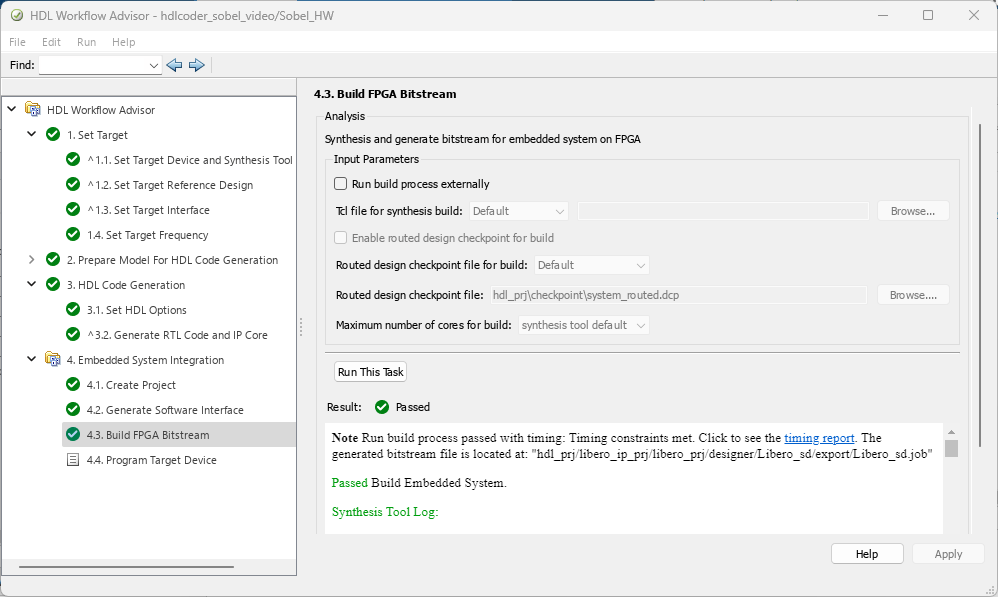
4. After you generate the bitstream, select the task 4.4 Program Target Device and click Run This Task to program the PolarFire SoC hardware. To download the FPGA bitstream to the PolarFire SoC board, set Programming method parameter to JTAG. When you power on the PolarFire SoC board, your design reloads on your SoC hardware.
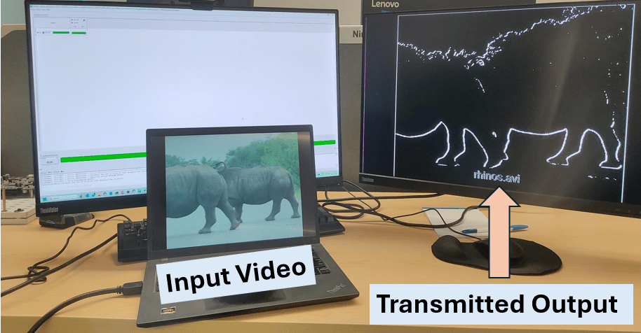
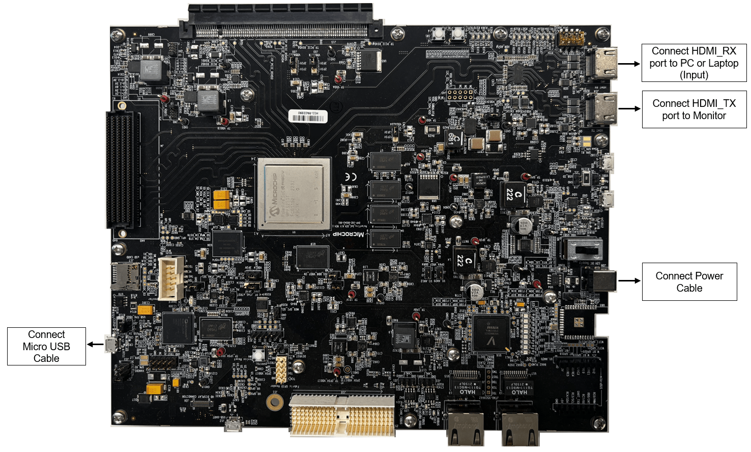
5. Connect the HDMI_RX port of PFSoC Video Kit to the computer where you want to play the input video. Connect the HDMI_TX port of PFSoC Video Kit to the monitor to see the transmitted output.
You can view edge detection of input image or video on the monitor connected to the HDMI_TX port. Below is the sample output for rhinos.avi input video.
Simulink Simulation
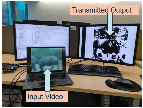
Transmitted Output from PolarFire SoC Video Kit