Microchip FPGA Board Support from HDL Verifier
HDL Verifier™ automates the verification of HDL code on FPGA boards by providing connections between your FPGA board and your simulations in Simulink® or MATLAB®.
FPGA-in-the-loop (FIL) enables you to run a Simulink or MATLAB simulation that is synchronized with an HDL design running on an FPGA board.
To use FPGA-in-the-loop, you must have a supported FPGA board connected to your MATLAB host computer using a supported connection type, and a supported synthesis tool.
Note
The HDL Verifier Support Package for Microchip FPGA Boards does not support board customization.
Supported Microchip FPGA Boards
This support package enables FPGA-in-the-loop simulation for the boards in the table.
| Device Family | Board | Ethernet | JTAG | PCI Express | Comments |
|---|---|---|---|---|---|
Microchip SmartFusion® 2 | Microchip SmartFusion 2 SoC FPGA Advanced Development Kit | ✓ | See Installing Microchip SmartFusion 2 SoC FPGA Advanced Development Kit | ||
Microchip Polarfire® | Microchip Polarfire Evaluation Kit | ✓ | See Installing Microchip Polarfire Evaluation Kit. | ||
Microchip RTG4® | RTG4-DEV-KIT | ✓ |
Installing Microchip SmartFusion 2 SoC FPGA Advanced Development Kit
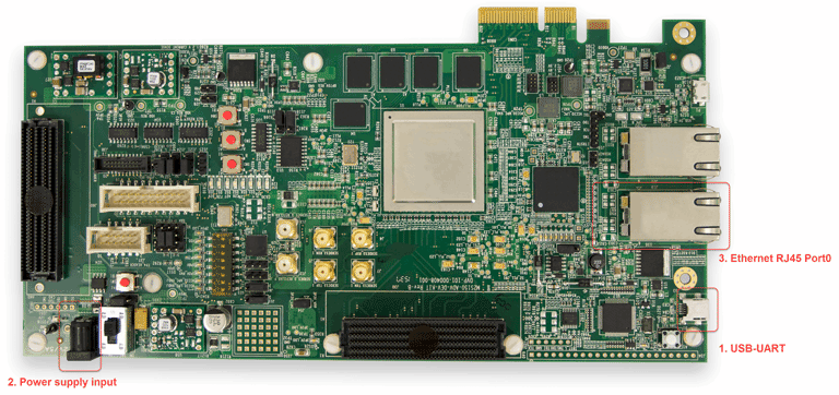
The Microchip SmartFusion 2 SoC FPGA Advanced Development Kit requires a special setup. Follow the following steps to ensure proper connection:
Board setup
To ensure functionality, connect the board and set it up as follows:

Connect the USB cable to the USB-UART terminal on the board.
Connect the power cable to the power supply input (12V DC).
Plug the RJ45 cable into RJ45-Port0.
Program the FPGA
Follow the steps using the FPGA-in-the-Loop Wizard to program the FPGA.
Installing Microchip Polarfire Evaluation Kit
The Microchip Polarfire Evaluation Kit requires a special setup. Follow the following steps to ensure proper connection:
Board setup
To ensure functionality, connect the board and set it up as follows:

Connect the USB cable to the J5 connector on the board.
Connect the power cable to the J9 jack on the board (12V DC , 5A).
Plug the RJ45 cable into RJ45-Port0 (J15 connector).
Set the jumpers on the board as follows:
J28 – closed
J27 – closed
J227 – closed
J26 – closed
J20 – 2-3 closed
J21 – 2-3 closed
J22 – 2-3 closed
J18 – 2-3 closed
J19- 2-3 closed
J23 – open
Program the FPGA
Follow the steps using the FPGA-in-the-Loop Wizard to program the FPGA.