Cosimulate Vivado FFT IP Core with Simulink
Using HDL Verifier™, you can set up cosimulation between Simulink® and an IP core from the AMD® Vivado® simulator. This setup allows you to design your Simulink algorithm to include an AMD IP implementation in the system and use Simulink as a testbench. To verify the IP core, you can use the specialized stimulus and visualization scopes from Simulink.
In this example, you use the Cosimulation Wizard to simulate and verify the behavior of a Fast Fourier Transform (FFT) IP core from the Vivado simulator in a Simulink environment. The FFT is an algorithm that transforms a signal in the time domain to its representation in the frequency domain.
To generate a Simulink block that represents the AMD IP core, you supply an HDL wrapper file and the Xilinx® Core Instance (XCI) file of the IP core to the Cosimulation Wizard. Once the block is generated, you can use it in Simulink to simulate the IP core behavior.
This example requires the Vivado simulator from AMD as well as Simulink, HDL Verifier, Fixed-Point Designer™, Signal Processing Toolbox™, and the DSP Systems Toolbox™. AMD Vivado must be on the MATLAB system path.
Step 1: Generate IP Core File
AMD IP cores can be referenced using XCI files. The first step for this cosimulation is to customize the FFT IP core and generate the corresponding XCI file. You can either use the provided Tcl script, gen_ip.tcl, or work interactively in Vivado to generate the XCI file.
To use the gen_ip.tcl file to generate the XCI File, open Vivado, and go to Tools > Run Tcl Script in the toolstrip. Select gen_ip.tcl in the window that opens. This step runs the script, creating a project called ip_prj and generating an XCI file named xfft_0.xci in:
"project_folder\ip_prj.srcs\sources_1\ip\xfft_0\"
Where "project_folder" is the folder in which the Vivado project ip_prj is stored. You can then proceed to Step 2: Create Wrapper HDL for IP Core.
To create the XCI file interactively, start by creating a new Vivado project. In the new project, under Project Manager, in Flow Navigator, click IP Catalog. Flow Navigator is usually on the left side of the Vivado Workspace.
The IP Catalog tab opens and lists the available Vivado AMD IP cores. In the search bar, look up FFT and select the entry labelled Fast Fourier Transform, which opens the Customize IP window.

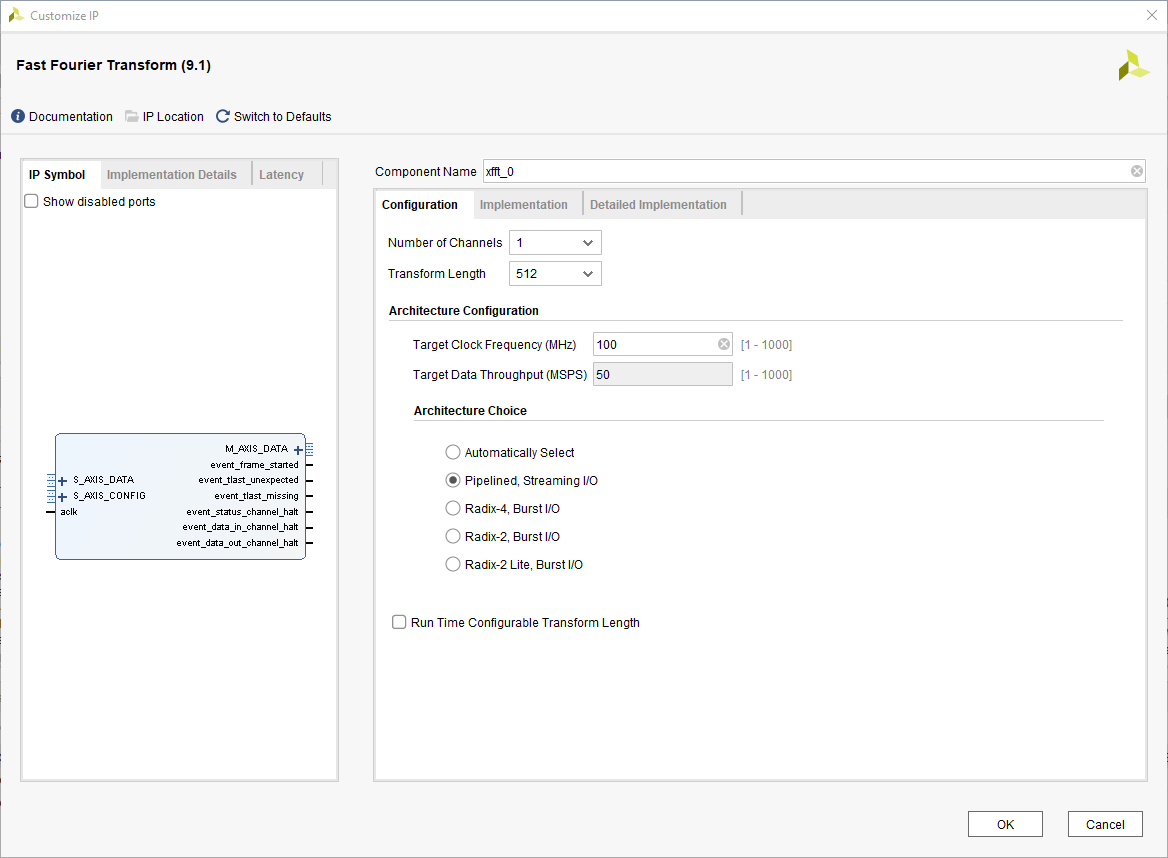
In the Customize IP window, make sure that Component Name is xfft_0. Then on the Configuration tab:
Change Transform Length to 512.
Change Target Clock Frequency (MHz) to
100.Change Architecture Choice to
Pipelined, Streaming I/O.

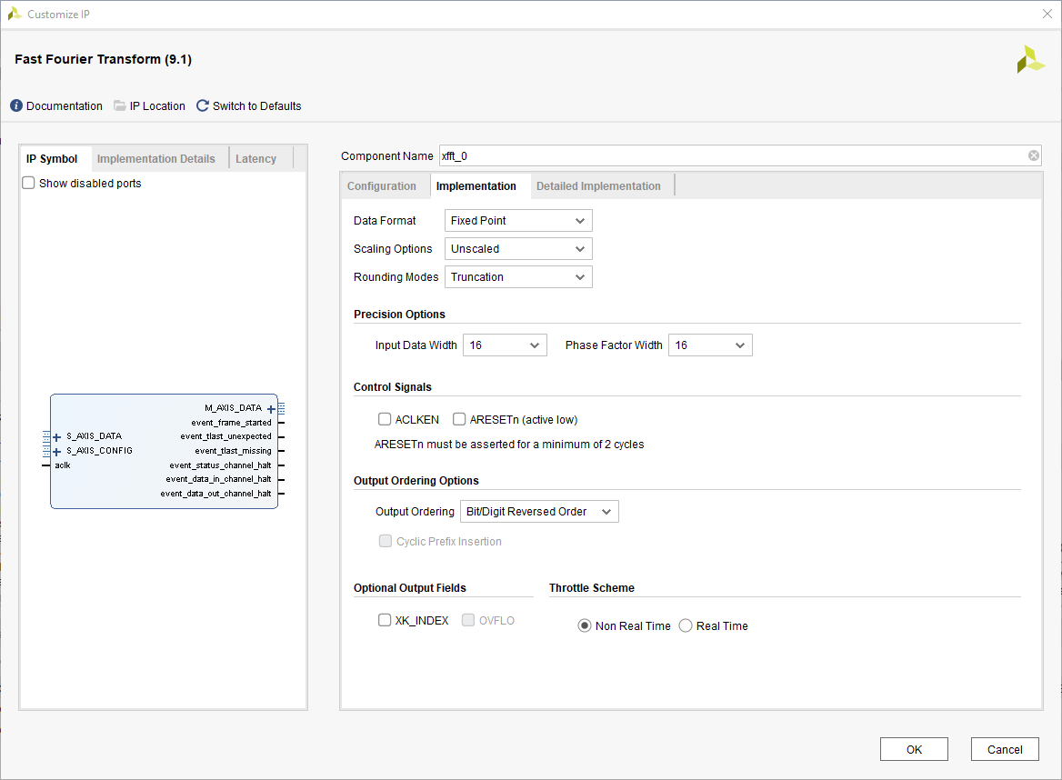
On the Implementation Tab:
Change Scaling Options to
Unscaled.

Accept the changes, then click Generate. Vivado generates the xfft_0.xci file and its corresponding target files, which are in:
"project_folder\project_name.srcs\sources_1\ip\xfft_0\"
Where "project_folder" is the folder in which the new Vivado project named "project_name" is stored.
Step 2: Create Wrapper HDL for IP Core
The Cosimulation Wizard requires a wrapper HDL file to generate the Simulink block. You wrap the AMD IP core with the HDL file, which acts as an intermediary between the Cosimulation Wizard and the IP core.
This example provides a wrapper file named my_fft.v. The wrapper file defines the block ports, instantiates the IP, and performs data preprocessing and signal routing to make the block easier to use.
To create a wrapper file, add the signals that you want to use in Simulink to the top-level declaration of the file. The Cosimulation Wizard uses the signals in this top-level declaration to define the ports of the block. The top-level ports in this image are the ports available in the block.

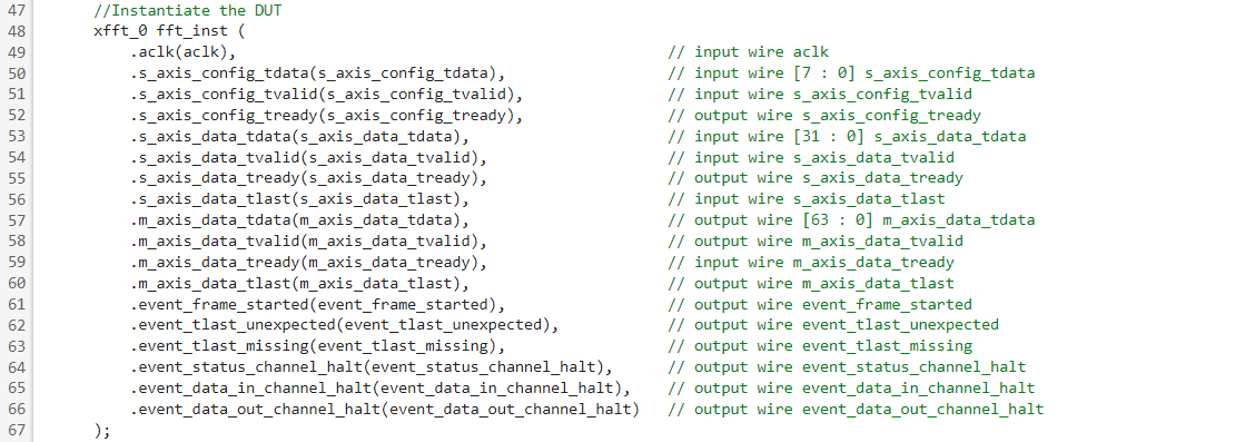
Next, instantiate the IP core as a device under test (DUT) inside of the wrapper file. Then assign the ports from the DUT to ports and wires in the wrapper file. These assignments link the data streams between the IP core and the generated Simulink block.

Your wrapper file could be as simple as instantiating the IP core as a DUT, and creating a one-to-one mapping between the DUT and top-level ports. However, you can also leverage the wrapper file to simplify the implementation in Simulink, if you know which ports of the IP core are unnecessary for your simulation.
Since components of this IP core, such as the configuration data and event data are unused or unchanged, these ports do not need to be available in Simulink. Instead, the wrapper file supplies constants to the IP core configuration, and hides the unused outputs by omitting their data ports from the top-level declaration.

This FFT IP core uses a specific method of data padding and concatenation to represent complex signals, instead of using separate real and imaginary components. Therefore, it has only one input data stream and one output data stream.
To simplify the supplied data in the Simulink environment, you can use the wrapper file to perform this concatenation and data padding for you. This arrangement allows your generated block to use separate real and imaginary components and abstracts the complex bit operations for the IP core, simplifying your model.

Step 3: Generate Simulink Block
Now you can use the Cosimulation Wizard to generate the Simulink block for cosimulation. To open the wizard, type the following command on the MATLAB command line.
cosimWizard
Alternatively, you can open the Cosimulation Wizard from the testbench model XilinxIPCosim.slx. In the Simulink toolstrip, select the Apps tab and click HDL Verifier. This action adds the HDL Verifier tab to the Simulink toolstrip. Then, in the Mode section, select HDL Cosimulation. Finally, to open the Cosimulation Wizard, click Import HDL Files in the Generate Cosim Block section.
In the Cosimulation Type page of the Cosimulation Wizard, change HDL Simulator to Vivado Simulator before proceeding to the next step, HDL Files.
Select the HDL file types from the drop-down list and add the wrapper HDL file my_fft.v. Then select the XCI file type in the file type drop-down list and add the core source file, xfft_0.xci.
You can use the default settings on the HDL Compilation, Simulation Options, and Input/Output Ports pages.
In the Output Port Details section, set all the outport Datatypes to Fixedpoint. Additionally, set the Sign of s_axis_data_tready and m_axis_data_tvalid to Unsigned. Then set Fraction Length on ports m_axis_data_tdata_re and m_axis_data_tdata_im to 15. These settings match the Simulink block output types with the data types from the IP core configuration.
Accept the default settings for the Clock/Reset Details and Start Time Alignment pages. However, in the Block Generations page, clear the option Automatically determine timescale at start of simulation and set it so that 1 second in Simulink = 10 ns in the HDL Simulator. This setting syncs the block so that one second in Simulink is equal to one clock cycle in the IP core implementation.
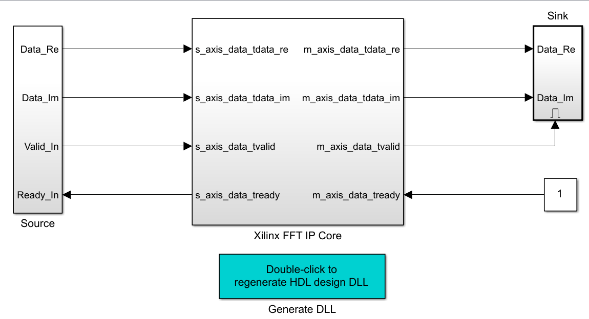
The Cosimulation Wizard generates an untitled Simulink model with two items: the Simulink block representation of the IP core and a method to regenerate the DLLs. The Cosimulation Wizard also generates a folder called xsim.dir in the current working folder, with all the files needed for Simulink cosimulation with the IP core.
Step 4: Run Cosimulation
Now that you have generated the necessary files and created the cosimulation block you can either create your own testbench, or use the provided Simulink testbench model, XilinxIPCosim.slx, to run the cosimulation and view the results.

The IP uses AXI4-Stream as the control interface. For this example, the full AXI4-Stream interface and protocol is not being simulated. Instead, in XilinxIPCosim.slx, the testbench assumes that the AXI4-Stream Manager Interface is always ready for new data. As long as the AXI4-Stream Subordinate Interface is ready for data, the model assumes that all data supplied is valid. The wrapper file handles the IP core configuration data by supplying constants to the relevant ports.
The model is set to run for 48 frames of FFT data to be processed by the FFT. The data input to the IP core block is a discrete sine wave, which changes its frequency from 100 kHz to 170 kHz in increments of 10 kHz. The 10 kHz frequency change occurs over 16 frames, and the shift from 100 kHz to 170 kHz is set to repeat every 16 frames.
To display the IP core output, the testbench uses a spectrum analyzer on the FFT output. When you run the testbench, notice a pair of shifting peaks, which slowly move away from the center frequency. This slow movement repeats twice, after the peaks return to the center for the first time. This behaviour reflects the changes in frequency occurring to the sine wave date input.

Summary
This example shows how to perform cosimulation between a AMD FFT IP core and Simulink. As long as you have generated the appropriate XCI files and created the HDL wrapper file, Simulink can perform cosimulation with AMD IP cores. This capability allows you to include AMD IP core functionality in your Simulink designs, and it provides the entire Simulink environment for testing and visualization of IP cores.
As this example also shows, you can avoid simulating the full AXI4-Stream control interface by simplifying the AXI-Stream signals to constants in Simulink and the wrapper file.
However, if your design requires full AXI4 signal functionality, you can implement all of the signals and drive them in the Simulink environment. Alternatively, you can include an internal transaction interface with an AXI BFM in your design, to add full AXI4 signal functionality but hide it from the Simulink environment.
Copyright 2022 The MathWorks, Inc.