Get Started with Simulink HDL Cosimulation
Set up an HDL Verifier™ application using the Cosimulation Wizard in the Simulink® environment.
The Cosimulation Wizard is a graphical user interface (GUI) that guides you through the process of generating a cosimulation block, System object™, or MATLAB® script.
In this example, you use Simulink and an HDL simulator to verify a design of a raised cosine filter written in Verilog®. The raised cosine filter is commonly used as a pulse shaping filter in digital communication systems. It produces no inter-symbol interference (ISI) for the input of modulated pulses.
To verify the functionality of this raised cosine filter, a Simulink testbench is provided. This testbench generates input to the HDL design under test (DUT) and plots the waveforms of both input and output.
The Cosimulation Wizard takes the provided Verilog file of this raised cosine filter as its input. It also collects user input required for setting up cosimulation in each step. At the end of the example, the Cosimulation Wizard generates a Simulink block that represents the HDL design in the Simulink model, a MATLAB script that compiles HDL design, and a MATLAB script that launches the HDL simulator for cosimulation. During simulation, you can watch the input and output waveforms of this HDL filter in Simulink.
The Cosimulation Wizard supports AMD® Vivado®, Siemens® ModelSim™ or Questa™, Cadence® Xcelium™, and Synopsys® VCS® HDL simulators.
Requirements and Prerequisites
This example requires Simulink and one of these HDL simulators to verify a register transfer level (RTL) design.
Vivado simulator from AMD
ModelSim or Questa from Siemens
Xcelium from Cadence
VCS from Synopsys
Launch Cosimulation Wizard
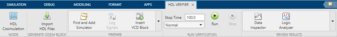
To launch the Cosimulation Wizard from the model, select the Apps tab in the Simulink toolstrip and click HDL Verifier. This action adds the HDL Verifier tab to the Simulink toolstrip. Then, in the Mode section, select HDL Cosimulation. Click Import HDL Files in the Generate Cosim Block section.
Configure HDL Cosimulation Block with Cosimulation Wizard
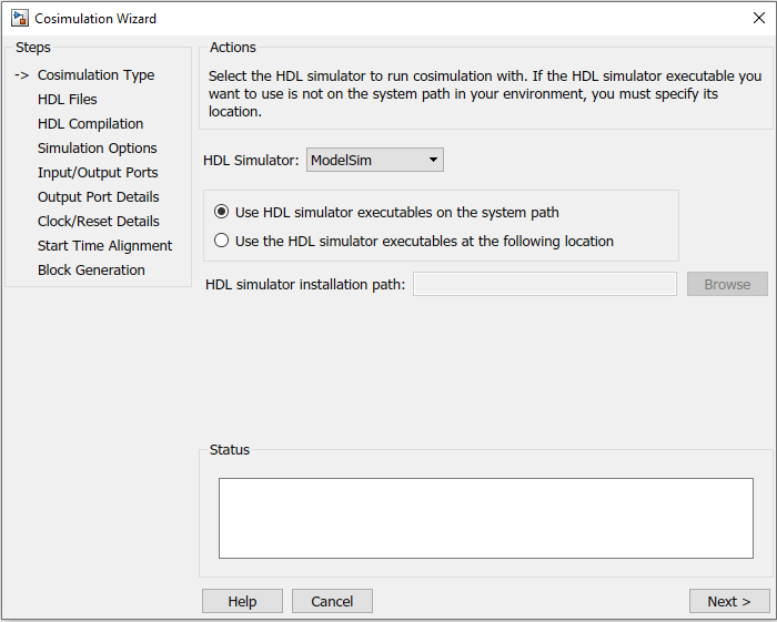
In the Cosimulation Type page, perform the following steps:
1.a). If you are using ModelSim or Questa, leave the HDL Simulator option as ModelSim.
b). If you are using Xcelium, change the HDL Simulator option to Xcelium.
c). If you are using Vivado simulator, change the HDL Simulator option to Vivado Simulator.
d). If you are using VCS, change the HDL Simulator option to VCS.
2. Leave the default option Use HDL simulator executables on the system path option if the HDL simulator executables appear on your system path. If these executables do not appear on the path, click on the Browse button to specify the location of these executables. In case of VCS, specify the VCS installation path, which is your VCS_HOME.
Click Next to proceed to the HDL Files page.
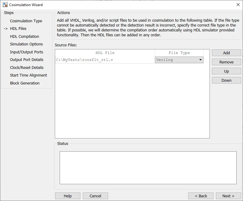
In the HDL Files page, perform the following steps:
ModelSim, Xcelium, or Vivado Simulator
Click Add and select either
rcostflt_rtl.vfor Verilog orrcosflt_rtl.vhdfor VHDL®.Review the file in the file list with the file type identified as you expected.
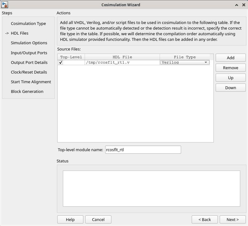
VCS
Click Add and select either
rcostflt_rtl.vfor Verilog orrcosflt_rtl.vhdfor VHDL.Review the file in the file list with the file type identified as you expected.
Select
rcostflt_rtl.vas Top-Level module.
For ModelSim, Xcelium, or Vivado simulator, click Next to proceed to the HDL Compilation page. For VCS, click Next to proceed to the Simulation Options page.
In the HDL Compilation page, the Cosimulation Wizard lists the default commands in the Compilation Commands window. You do not need to change these commands for this tutorial.
When you run the Cosimulation Wizard with your own code, you may add or change the compilation commands in this window.
The following figure shows the compilation commands for ModelSim.

Click Next. The MATLAB console displays the compilation log. If an error occurs during compilation, that error appears in the status area.
VCS
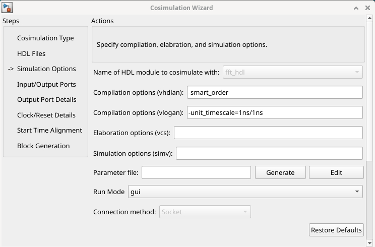
For VCS, compilation and simulation combine into a single step. Specify compilation options for VHDL or Verilog, elaboration options, or simulation options in this step.
If you want to use HDL parameters, you can click Generate next to the Parameter file section to generate a file with default values. Then, click Edit to edit the file.
The following figure shows the compilation and simulation commands for VCS.
ModelSim or Xcelium
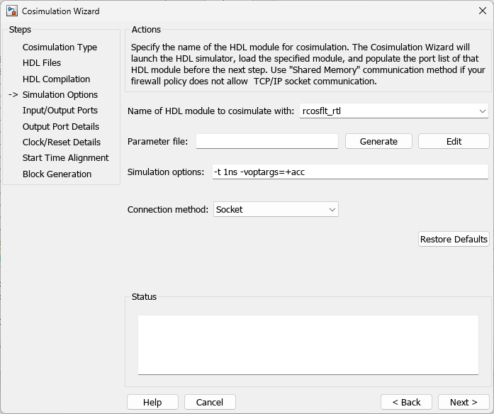
Specify the name of the HDL module/entity for cosimulation. From the drop-down list, select
rcosflt_rtl. This module is the Verilog/VHDL module you use for cosimulation. If you do not seercosflt_rtlin the drop-down list, you can enter the file name manually.For Connection method, select
Shared Memoryif your firewall policy does not allow TCP/IP socket communication.
Vivado Simulator
By default, name of the module is set to
rcosflt_rtl. This module is the Verilog/VHDL module you use for cosimulation.Set Debug internal signals to
offand HDL time precision to1psfor this example.

Click Next to proceed to the Simulink Ports pane. The Cosimulation Wizard launches the HDL simulator in the background console using the specified HDL module and simulation options. After the wizard launches the HDL simulator, the wizard populates the input and output ports on the Verilog/VHDL module rcosflt_rtl and displays them in the next step.
In the Specify Port Types step, the Cosimulation Wizard displays two tables containing the input and output ports of rcostflt_rtl, respectively.

The Cosimulation Wizard attempts to identify the port type of each port. If the wizard incorrectly identifies a port, you can change the port type using these tables.
For input ports, you can select from
Clock,Reset,Input, orUnused. HDL Verifier connects only the input ports markedInputsto Simulink during cosimulation.HDL Verifier connects output ports marked
Outputwith Simulink during cosimulation. The wizard and Simulink ignore those output ports markedUnusedduring cosimulation.You can change the parameters for signals identified as
ClockandResetat a later step.
Accept the default port types and click Next to proceed to the Output Port Details page.
In the Output Port Details page, perform the following steps:
Set the sample time of
filter_outto-1to inherit via back propagation.You can see from the Verilog code that the Cosimulation Wizard represents the output in a
sfix34_En29format. Change the following fields:
Data Type to
FixedpointSign to
SignedFraction Length to
29

Click Next to proceed to the Clock/Reset Details page.
In the Clock/Reset page, perform the following steps.
ModelSim, Xcelium, or VCS
Set HDL time unit to
ns.Set clock period to 20.
Leave or set active edge to
Rising.Leave or set reset initial value to 1.
Set reset signal duration to 15.

Vivado Simulator
Set the HDL time unit to
ps.Set the clock period to 20.
Leave or set the active edge to
Rising.Leave or set the reset initial value to 1.
Set the reset signal duration to 15.
Click Next to proceed to the Start Time Alignment page.
The Start Time Alignment page displays a plot for the waveforms of clock and reset signals. The Cosimulation Wizard shows the HDL time to start cosimulation with a red line. The start time is also the time at which the Simulink gets the first input sample from the HDL simulator.
In the Start Time Alignment page, set the alignment. The active edge of our clock is a rising edge. Thus, at time 20 ns in the ModelSim or Xcelium (20 ps in the Vivado simulator), the registered output of the raised cosine filter is stable. No race condition exists, and the default HDL time to start cosimulation is what we want for this simulation. You do not need to make any changes to the start time.

Click Next to proceed to Block Generation.
Before you generate the HDL Cosimulation block, you have the option to determine the timescale before you finish the Cosimulation Wizard. Alternately, you can instruct HDL Verifier to calculate a timescale later. Timescale calculation by the verification software occurs after you connect all the input/output ports of the generated HDL Cosimulation block and start simulation.
In the Block Generation page, perform the following steps.
ModelSim or Xcelium
Leave Automatically determine timescale at start of simulation selected (default). Later, you will have the opportunity to view the calculated timescale and change that value before you begin simulation.

Vivado Simulator
Uncheck Automatically determine the timescale at start of simulation and set the timescale by setting 1 second in Simulink corresponds to to 2e-11 s in the HDL simulator.

VCS
Set the timescale by setting 1 second in Simulink corresponds to to 20 ns in the HDL simulator.

Click Finish to complete the Cosimulation Wizard session.
Create Testbench to Verify HDL Design
In this example, the Simulink testbench model rcosflt_tb has been provided. After you click Finish in the Cosimulation Wizard, Simulink inserts the following items at the center of the model canvas:
An HDL Cosimulation block
A block to recompile the HDL design (contains a link to a script that is launched by double-clicking the block)
A block to launch the HDL simulator (contains a link to a script that is launched by double-clicking the block) (For Modelsim and Xcelium only)
Position the HDL Cosimulation block so that the constant and convert blocks line up as inputs to the HDL Cosimulation block and the bus lines up as output. Connect the blocks. Your model now looks similar to that in the following figure.

Run Cosimulation and Verify HDL Design
ModelSim or Xcelium
Launch the HDL simulator by double-clicking the block labeled Launch HDL Simulator.
When the HDL simulator is ready, return to Simulink and start simulation.
Determine timescale. Recall that you selected Automatically determine timescale at start of simulation option on the last page of the Cosimulation Wizard. When doing so, HDL Verifier launches the Timescale Details graphical interface instead of starting the simulation. Both the HDL simulator and Simulink sample the
filter_inandfilter_outports at 1 second. However, their sample time in the HDL simulator should be the same as the clock period (20 ns). Change the Simulink sample time of/rcosflt_rtl/clkto 1 (seconds), and press Enter. The wizard then updates the table. The following figure shows the new timescale: 1 second in Simulink corresponds to 2e-008 s in the HDL simulator.

Click OK to close the Timescale Details dialog box. Restart Simulink simulation and verify the results from the scope in the testbench model.
Vivado Simulator
In the Simulink toolstrip, on the Simulation tab, click run to start the simulation. There is no separate process for the HDL simulation, since the Simulink block executes a single process with a shared DLL.
VCS
Compile HDL design by double-clicking the block labeled Compile HDL Design.
Launch the HDL simulator by double-clicking the block labeled Launch HDL Simulator.
When the HDL simulator is ready, type
runcommand in tcl console.Return to Simulink and start simulation.
The scope displays both the delayed version of input to raised cosine filter and that filter's output. If you sample the output of this filter output directly, no inter-symbol-interference occurs.

See Also