Cylinder Cushion (TL)
Libraries:
Simscape /
Fluids /
Thermal Liquid /
Actuators /
Auxiliary Components
Description
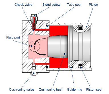
The Cylinder Cushion (TL) block models a cylinder cushion in a thermal liquid network. The cushion decelerates the cylinder rod as it approaches the end of a stroke by restricting the flow rate leaving the cylinder chamber. This figure below shows a typical cylinder cushion design [1].

As the piston moves toward the cap, which is to the left in the figure, the cushioning bush, or plunger, enters the chamber in the cap and creates an additional resistance to the fluid leaving the cylinder chamber. The piston deceleration starts when the plunger enters the opening in the cap and closes the main fluid exit. In this state, the fluid flows through a check valve in the gap between the cylinder and the cap. The valve restricts the flow rate leaving the cylinder chamber and reduces the initial speed of the piston.
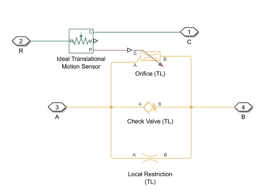
The cylinder cushion is a composite of a variable orifice, a local restriction, and a check valve. The variable orifice provides a variable opening between the plunger and end cap cavity. The local restriction connects the piston chamber to the cushion chamber. The check valve provides a flow path between the cushion chamber and the piston chamber only during piston retraction.
The Cylinder Cushion (TL) block is a composite component that consists of these blocks:
A Local Restriction (TL) block that models the cushioning valve.
A Check Valve (TL) block that models the check valve.
An Orifice (TL) block that models the variable gap between the plunger and the end cap.
An Ideal Translational Motion Sensor block that converts the separation between the plunger and the cavity in the end cap into a physical signal. This signal controls the opening of the Orifice (TL) block.

You can use the Cylinder Cushion (TL) block to model actuators. A single-acting or double-acting actuator can include cylinder cushions to slow piston motion near the ends of the stroke. The cylinder cushion prevents extreme impacts when the piston is stopped by the end caps.
Ports A and B are thermal liquid conserving ports associated with the chamber inlet and outlet, respectively. Port R is a mechanical translational conserving port connected with the piston plunger. Port C is a mechanical translational conserving port that corresponds to the cylinder clamping structure. The block cushions the flow rate from port B to port A. The check valve in the block is oriented from port A to port B.
Variable Orifice Area
In the variable orifice, the block assumes that when the plunger is far away from the cushion, the orifice area is fully open and equal to , where Dplunger is the diameter of the circular plunger. When the plunger is in the cushion, the orifice is fully closed and the orifice area is equal to the leakage area. As the plunger moves towards the cushion, the fluid flows radially from the cylinder chamber to the cap chamber through the gap between the plunger and the opening in the cap. The block assumes that the orifice area changes linearly with the piston displacement between the maximum area and the leakage area. The orifice area for a given position of the piston is
where:
S is the orifice area for a given position of the piston.
Sleak is the value of the Leakage area between plunger and cushion sleeve parameter.
Smax is the maximum size of the orifice, which is equal to the value of the Cushion plunger cross-sectional area parameter.
xpiston is the displacement of the piston. The initial displacement of the piston x0,piston is the value of the Actuator piston initial displacement parameter.
ε is
1when the Actuator mechanical orientation parameter isPressure at A causes positive displacement of R relative to Cand is-1when the Actuator mechanical orientation parameter isPressure at A causes negative displacement of R relative to C.Lplunger is the value of the Cushion plunger length parameter.
Dplunger is the value of the Cushion plunger diameter parameter.
Numerically-Smoothed Area and Pressure
You can maintain numerical robustness in your simulation by adjusting the Smoothing factor parameter. If the Smoothing factor parameter is nonzero, the block smooths the orifice area and the check valve pressure range. The block smoothly saturates the orifice area between the Leakage area between plunger and cushion sleeve and Cushion plunger cross-sectional area parameters. The valve pressure is saturated between the Check valve cracking pressure differential and Check valve maximum pressure differential parameters. For more information, see Numerical Smoothing.
Ports
Conserving
Parameters
References
[1] Rohner, P. Industrial Hydraulic Control. Fourth edition. Brisbane: John Wiley & Sons, 1995.
Extended Capabilities
Version History
Introduced in R2023b
