Double-Acting Actuator (MA)
Libraries:
Simscape /
Fluids /
Moist Air /
Actuators
Description
The Double-Acting Actuator (MA) block models a linear actuator with a piston controlled by two opposing moist air chambers. The actuator generates force in the extension and retraction strokes. The generated force depends on the pressure difference between the two chambers.
The figure shows the key components of the actuator. Ports A and B represent the moist air chamber inlets. Port R represents the translating actuator piston and port C represents the actuator case. Ports HA and HB represent the thermal interfaces between each moist air chamber and the environment. The moving piston is adiabatic.
Displacement
The block measures the piston displacement as the position at port
R relative to port C. The
Mechanical orientation parameter identifies the direction
of piston displacement. The piston displacement is neutral, or 0
,
when the chamber A volume is equal to the value of the Dead volume in
chamber A parameter. When the Piston displacement from
chamber A cap parameter is Provide input signal from
Multibody joint
, you input the piston displacement using port
p. Ensure that the derivative of the position signal is
equal to the piston velocity. You can ensure that the derivative of the position
signal is equal to the piston velocity by using a Translational Multibody Interface block to
provide the piston displacement.
The direction of the piston motion depends on the Mechanical orientation parameter. If the mechanical orientation is positive, then the piston translation is positive in relation to the actuator case when the gauge pressure at port A is positive. The direction of motion reverses when the mechanical orientation is negative.
Hard Stop
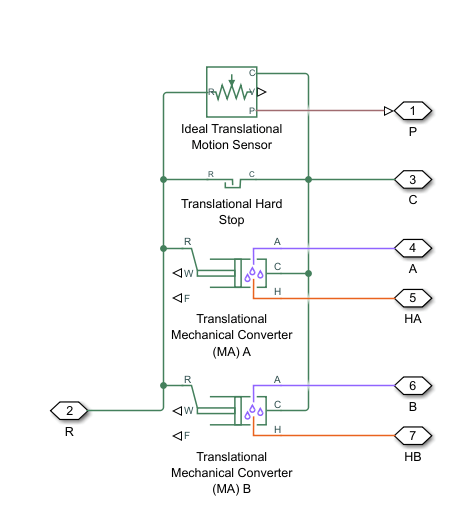
A set of hard stops limit the piston range of motion. The block uses an implementation of the Translational Hard Stop block, which treats hard stops like spring-damper systems. The spring stiffness coefficient controls the restorative component of the hard-stop contact force and the damping coefficient the dissipative component.
The hard stops are located at the distal ends of the piston stroke. If the mechanical orientation is positive, then the lower hard stop is at x = 0, and the upper hard stop is at x = +stroke. If the mechanical orientation is negative, then the lower hard stop is at x = -stroke, and the upper hard stop is at x = 0.
Block Composite
This block is a composite component based on these Simscape™ Foundation blocks:
Ports
Input
p — Piston position input, m
physical signal
Physical signal input associated with the piston position, in m. Connect this port to a Simscape Multibody™ network using a Translational Multibody Interface block.
Dependencies
To enable this port, set Piston displacement from
chamber A cap to Provide input signal
from Multibody joint
.
Output
p — Piston position, m
physical signal
Physical signal port associated with the piston position.
Dependencies
To enable this port, set Piston displacement from
chamber A cap to Calculate from velocity
of port R relative to port C
.
Conserving
A — Liquid port
moist air
Moist air conserving port associated with the inlet to chamber A.
B — Liquid port
moist air
Moist air conserving port associated with the inlet to chamber B.
R — Actuator piston
mechanical translational
Mechanical translational conserving port associated with the actuator piston.
C — Actuator casing
mechanical translational
Mechanical translational conserving port associated with the actuator casing.
HA — Heat transfer
thermal
Thermal conserving port associated with chamber A.
HB — Heat transfer
thermal
Thermal conserving port associated with chamber B.
Parameters
Actuator
Same fluid on both sides — Option to model same fluid in both chambers
on
(default) | off
Whether to model the same fluid in both actuator chambers. If you select this parameter, the actuator propagates fluid properties through both chambers. Clear this parameter to model each chamber as a different fluid, where each chamber is connected to an isolated fluid network.
Mechanical orientation — Piston displacement direction
Pressure at A causes positive
displacement of R relative to C
(default) | Pressure at A causes negative displacement of R relative
to C
Piston displacement direction. When you set this parameter to:
Pressure at A causes positive displacement of R relative to C
, the piston displacement is positive when the volume of moist air at port A is expanding. This motion corresponds to rod extension.Pressure at A causes negative displacement of R relative to C
, the piston displacement is negative when the volume of moist air at port A is expanding. This motion corresponds to rod contraction.
Piston cross-sectional area in chamber A — Chamber A piston area
0.01 m^2
(default) | positive scalar
Cross-sectional area of the piston rod on the chamber A side.
Piston cross-sectional area in chamber B — Chamber B piston area
0.01 m^2
(default) | positive scalar
Cross-sectional area of the piston rod on the chamber B side.
Piston stroke — Maximum piston travel distance
0.1 m
(default) | positive scalar
Maximum piston travel distance.
Dead volume in chamber A — Chamber A fluid volume at full piston retraction
1e-5 m^3
(default) | positive scalar
Volume of moist air when the piston displacement is
0
in chamber A. This parameter is the moist air
volume when the piston is against the actuator end cap.
Dead volume in chamber B — Chamber B fluid volume at full piston retraction
1e-5 m^3
(default) | positive scalar
Volume of moist air when the piston displacement is
0
in chamber B. This parameter is the moist air
volume when the piston is against the actuator end cap.
Cross-sectional area at port A — Area at port A
0.01 m^2
(default) | positive scalar
Cross-sectional area of port A.
Cross-sectional area at port B — Area at port B
0.01 m^2
(default) | positive scalar
Cross-sectional area of port B.
Environment pressure specification — Reference environment pressure
Atmospheric
pressure
(default) | Specified pressure
Environment reference pressure. When you select
Atmospheric pressure
, the block assumes a
pressure of 0.101325 MPa.
Environment pressure — User-defined environmental pressure
0.101325 MPa
(default) | positive scalar
User-defined environmental pressure.
Dependencies
To enable this parameter, set Environment pressure
specification to Specified
pressure
.
Hard Stop
Hard stop model — Hard stop model
Stiffness and damping applied smoothly
through transition region, damped rebound
(default) | Full stiffness and damping applied at bounds, undamped
rebound
| Full stiffness and damping applied at bounds, damped
rebound
| Based on coefficient of
restitution
Hard stop model to use when the piston is at full extension or full extraction. See the Translational Hard Stop block for more information.
Hard-stop stiffness coefficient — Stiffness coefficient
1e10
N/m
(default) | positive scalar
Piston stiffness coefficient.
Dependencies
To enable this parameter, set Hard stop model to one of these settings:
Stiffness and damping applied smoothly through transition region, damped rebound
Full stiffness and damping applied at bounds, undamped rebound
Full stiffness and damping applied at bounds, damped rebound
Hard-stop damping coefficient — Damping coefficient
150
N*s/m
(default) | positive scalar
Piston damping coefficient.
Dependencies
To enable this parameter, set Hard stop model to one of these settings:
Stiffness and damping applied smoothly through transition region, damped rebound
Full stiffness and damping applied at bounds, undamped rebound
Full stiffness and damping applied at bounds, damped rebound
Transition region — Application range of hard stop force model
0.1
mm
(default) | positive scalar
Application range of the hard stop force model. The block does not apply the hard stop model when the maximum extension or retraction of the piston is outside of this range. In this situation, there is no additional force on the piston.
Dependencies
To enable this parameter, set Hard stop model
to Stiffness and damping applied smoothly through
transition region, damped rebound
.
Coefficient of restitution — Ratio of final-to-initial relative speed between slider and stop after collision
0.7
(default) | unitless value between 0 and 1
Ratio of the final to the initial relative speed between the slider and the stop after the slider bounces.
Dependencies
To enable this parameter, set Hard stop model
to Based on coefficient of
restitution
.
Static contact speed threshold — Threshold relative speed between slider and stop before collision
0.001 m/s
(default) | nonnegative scalar
Threshold relative speed between the slider and stop before collision.
When the slider hits the case with a speed less than the value of the
Static contact speed threshold parameter, they
stay in contact. Otherwise, the slider bounces. To avoid modeling static
contact between the slider and the case, set this parameter to
0
.
Dependencies
To enable this parameter, set Hard stop model
to Based on coefficient of
restitution
.
Static contact release force threshold — Force needed to transition from contact mode to free mode
0.001 N
(default) | positive scalar
Minimum force needed to release the slider from a static contact mode.
Dependencies
To enable this parameter, set Hard stop model
to Based on coefficient of
restitution
.
Initial Conditions for Chamber A
Piston displacement from chamber A cap — Method for determining piston position
Calculate from velocity of port R
relative to port C
(default) | Provide input signal from Multibody
joint
Method for determining the piston position. The block can receive the
position from a Multibody block when set to Provide input
signal from Multibody joint
, or can calculate the
position internally and report the position at port
p. The position is between 0
and the value of the Piston stroke parameter when
the mechanical orientation is positive and between 0
and the negative value of the Piston stroke
parameter when the mechanical orientation is negative.
Initial piston displacement from chamber A cap — Piston displacement at start of simulation
0
m
(default) | scalar
Piston position at the start of the simulation with respect to the chamber A cap.
Dependencies
To enable this parameter, set Piston
displacement to Calculate from velocity
of port R relative to port C
.
Initial moist air pressure in chamber A — Moist air pressure at start of simulation
0.101325
MPa
(default) | positive scalar
Moist air pressure at the start of the simulation in chamber A.
Initial moist air temperature in chamber A — Moist air temperature at start of simulation
293.15
K
(default) | scalar
Moist air temperature at the start of simulation in chamber A.
Initial humidity specification in chamber A — Quantity to use to describe initial humidity level
Relative humidity
(default) | Specific humidity
| Mole fraction
| Humidity ratio
| Wet-bulb temperature
Whether to describe the initial moist air humidity level in chamber A using the relative humidity, specific humidity, water vapor mole fraction, or humidity ratio.
Initial moist air relative humidity in chamber A — Relative humidity at start of simulation
0.5
(default) | scalar in the range [0,1]
Moist air relative humidity at the start of simulation in chamber A.
Dependencies
To enable this parameter, set Initial humidity
specification in chamber A to Relative
humidity
.
Initial moist air specific humidity in chamber A — Specific humidity at start of simulation
0.01
(default) | scalar in the range [0,1]
Moist air specific humidity, defined as the mass fraction of water vapor in a moist air mixture, at the start of simulation in chamber A.
Dependencies
To enable this parameter, set Initial humidity
specification in chamber A to Specific
humidity
.
Initial moist air water vapor mole fraction in chamber A — Mole fraction of water vapor at start of simulation
0.01
(default) | scalar in the range [0,1]
Mole fraction of the water vapor in a moist air mixture at the start of simulation in chamber A.
Dependencies
To enable this parameter, set Initial humidity
specification in chamber A to Mole
fraction
.
Initial moist air humidity ratio in chamber A — Humidity ratio at start of simulation
0.01
(default) | scalar in the range [0,1]
Moist air humidity ratio, defined as the mass ratio of water vapor to dry air and trace gas, at the start of simulation in chamber A.
Dependencies
To enable this parameter, set Initial humidity
specification in chamber A to Humidity
ratio
.
Initial moist air wet-bulb temperature in chamber A — Wet-bulb temperature at start of simulation
287
K
(default) | positive scalar
Wet-bulb temperature of the moist air mixture at the start of simulation.
Dependencies
To enable this parameter, set Initial humidity
specification in chamber A to Wet-bulb
temperature
.
Initial trace gas specification in chamber A — Quantity to use to describe initial trace gas level
Mass fraction
(default) | Mole fraction
Whether to use the mass fraction or mole fraction to describe the trace gas level in chamber A at the start of simulation.
Initial trace gas mass fraction in chamber A — Mass fraction of trace gas at start of simulation
0.001
(default) | scalar in the range [0,1]
Mass fraction of the trace gas in a moist air mixture at the start of simulation in chamber A.
Dependencies
To enable this parameter, set Initial trace gas
specification to Mass
fraction
.
Initial trace gas mole fraction in chamber A — Mole fraction of trace gas at start of simulation
0.001
(default) | scalar in the range [0,1]
Mole fraction of the trace gas in a moist air mixture at the start of simulation in chamber A.
Dependencies
To enable this parameter, set Initial trace gas
specification in chamber A to Mole
fraction
.
Initial mass ratio of water droplets to moist air in chamber A — Ratio of water droplets to moist air
0
(default) | positive scalar
Initial mass ratio of water droplets to moist air.
Relative humidity at saturation in chamber A — Relative humidity above which condensation occurs
1
(default) | positive scalar
Relative humidity above which condensation occurs in chamber A.
Water vapor condensation time constant in chamber A — Time scale for condensation
1e-3 s
(default) | positive scalar
Characteristic time scale at which an oversaturated moist air volume returns to saturation by condensing out excess humidity.
Water droplets evaporation time constant in chamber A — Time scale for evaporation
1e-3 s
(default) | positive scalar
Characteristic time scale at which water droplets evaporate to vapor.
Fraction of condensate entrained as water droplets in chamber A — Fraction of condensate in water droplets
1
(default) | scalar in the range [0,1]
Fraction of the condensate in the moist air that is entrained as water droplets.
Initial Conditions for Chamber B
Initial moist air pressure in chamber B — Moist air pressure at start of simulation
0.101325
MPa
(default) | positive scalar
Moist air pressure at the start of the simulation in chamber B.
Initial moist air temperature in chamber B — Moist air temperature at start of simulation
293.15
K
(default) | scalar
Moist air temperature at the start of simulation in chamber B.
Initial humidity specification in chamber B — Quantity to use to describe initial humidity level
Relative humidity
(default) | Specific humidity
| Mole fraction
| Humidity ratio
| Wet-bulb temperature
Whether to describe the initial moist air humidity level in chamber B using the relative humidity, specific humidity, water vapor mole fraction, or humidity ratio.
Initial moist air relative humidity in chamber B — Relative humidity at start of simulation
0.5
(default) | scalar in the range [0,1]
Moist air relative humidity at the start of simulation in chamber B.
Dependencies
To enable this parameter, set Initial humidity
specification in chamber B to Relative
humidity
.
Initial moist air specific humidity in chamber B — Specific humidity at start of simulation
0.01
(default) | scalar in the range [0,1]
Moist air specific humidity, defined as the mass fraction of water vapor in a moist air mixture, at the start of simulation in chamber B.
Dependencies
To enable this parameter, set Initial humidity
specification in chamber B to Specific
humidity
.
Initial moist air water vapor mole fraction in chamber B — Mole fraction of water vapor at start of simulation
0.01
(default) | scalar in the range [0,1]
Mole fraction of the water vapor in a moist air mixture at the start of simulation in chamber B.
Dependencies
To enable this parameter, set Initial humidity
specification in chamber B to Mole
fraction
.
Initial moist air humidity ratio in chamber B — Humidity ratio at start of simulation
0.01
(default) | scalar in the range [0,1]
Moist air humidity ratio, defined as the mass ratio of water vapor to dry air and trace gas, at the start of simulation in chamber B.
Dependencies
To enable this parameter, set Initial humidity
specification in chamber B to Humidity
ratio
.
Initial moist air wet-bulb temperature in chamber B — Wet-bulb temperature at start of simulation
287
K
(default) | positive scalar
Wet-bulb temperature of the moist air mixture at the start of simulation.
Dependencies
To enable this parameter, set Initial humidity
specification in chamber B to Wet-bulb
temperature
.
Initial trace gas specification in chamber B — Quantity to use to describe initial trace gas level
Mass fraction
(default) | Mole fraction
Whether to use the mass fraction or mole fraction to describe the trace gas level in chamber B at the start of simulation.
Initial trace gas mass fraction in chamber B — Mass fraction of trace gas at start of simulation
0.001
(default) | scalar in the range [0,1]
Mass fraction of the trace gas in a moist air mixture at the start of simulation in chamber B.
Dependencies
To enable this parameter, set Initial trace gas
specification to Mass
fraction
.
Initial trace gas mole fraction in chamber B — Mole fraction of trace gas at start of simulation
0.001
(default) | scalar in the range [0,1]
Mole fraction of the trace gas in a moist air mixture at the start of simulation in chamber B.
Dependencies
To enable this parameter, set Initial trace gas
specification in chamber B to Mole
fraction
.
Initial mass ratio of water droplets to moist air in chamber B — Ratio of water droplets to moist air
0
(default) | positive scalar
Initial mass ratio of water droplets to moist air.
Relative humidity at saturation in chamber B — Relative humidity above which condensation occurs
1
(default) | positive scalar
Relative humidity above which condensation occurs in chamber B.
Water vapor condensation time constant in chamber B — Time scale for condensation
1e-3 s
(default) | positive scalar
Characteristic time scale at which an oversaturated moist air volume returns to saturation by condensing out excess humidity.
Water droplets evaporation time constant in chamber B — Time scale for evaporation
1e-3 s
(default) | positive scalar
Characteristic time scale at which water droplets evaporate to vapor.
Fraction of condensate entrained as water droplets in chamber B — Fraction of condensate in water droplets
1
(default) | scalar in the range [0,1]
Fraction of the condensate in the moist air that is entrained as water droplets.
Extended Capabilities
C/C++ Code Generation
Generate C and C++ code using Simulink® Coder™.
Version History
Introduced in R2024aR2024b: Model water droplets suspended in moist air flow
Blocks in the moist air domain can now model water droplets suspended in a moist air flow. To model water droplets, select Enable entrained water droplets in the Moist Air Properties (MA) block connected to your moist air network.
MATLAB Command
You clicked a link that corresponds to this MATLAB command:
Run the command by entering it in the MATLAB Command Window. Web browsers do not support MATLAB commands.
Select a Web Site
Choose a web site to get translated content where available and see local events and offers. Based on your location, we recommend that you select: .
You can also select a web site from the following list
How to Get Best Site Performance
Select the China site (in Chinese or English) for best site performance. Other MathWorks country sites are not optimized for visits from your location.
Americas
- América Latina (Español)
- Canada (English)
- United States (English)
Europe
- Belgium (English)
- Denmark (English)
- Deutschland (Deutsch)
- España (Español)
- Finland (English)
- France (Français)
- Ireland (English)
- Italia (Italiano)
- Luxembourg (English)
- Netherlands (English)
- Norway (English)
- Österreich (Deutsch)
- Portugal (English)
- Sweden (English)
- Switzerland
- United Kingdom (English)
Asia Pacific
- Australia (English)
- India (English)
- New Zealand (English)
- 中国
- 日本Japanese (日本語)
- 한국Korean (한국어)