Main Content

Point

Point annotation

Since R2024a

    Description

    A Point object labels points in a volume display. The properties of the object control the appearance and behavior of the point annotation. You can create a Point object interactively from the Viewer toolstrip. For details, see Label Volume Display Using Point and Line Annotations.

    Creation

    Description

    p = images.ui.graphics.roi.Point creates a Point object with default property values. Use p to query and modify properties of the Point object after you create the object. To display the annotation, add p to the Annotations property of a Viewer object.

    example

    p = images.ui.graphics.roi.Point(Name=Value) sets properties of the object using one or more name-value arguments. For example, images.ui.graphics.roi.Point(Position=[35 3 1012]) creates a point annotation at the specified xyz-location.

    Properties

    expand all

    Color of the point annotation, specified as an RGB triplet, a hexadecimal color code, a color name, or a short color name. The default color is orange, defined by the RGB triplet [0.85 0.325 0.098].

    For a custom color, specify an RGB triplet or a hexadecimal color code.

    • An RGB triplet is a three-element row vector whose elements specify the intensities of the red, green, and blue components of the color. The intensities must be in the range [0,1], for example, [0.4 0.6 0.7].

    • A hexadecimal color code is a string scalar or character vector that starts with a hash symbol (#) followed by three or six hexadecimal digits, which can range from 0 to F. The values are not case sensitive. Therefore, the color codes "#FF8800", "#ff8800", "#F80", and "#f80" are equivalent.

    Alternatively, you can specify some common colors by name. This table lists the named color options, the equivalent RGB triplets, and hexadecimal color codes.

    Color NameShort NameRGB TripletHexadecimal Color CodeAppearance
    "red""r"[1 0 0]"#FF0000"

    Sample of the color red

    "green""g"[0 1 0]"#00FF00"

    Sample of the color green

    "blue""b"[0 0 1]"#0000FF"

    Sample of the color blue

    "cyan" "c"[0 1 1]"#00FFFF"

    Sample of the color cyan

    "magenta""m"[1 0 1]"#FF00FF"

    Sample of the color magenta

    "yellow""y"[1 1 0]"#FFFF00"

    Sample of the color yellow

    "black""k"[0 0 0]"#000000"

    Sample of the color black

    "white""w"[1 1 1]"#FFFFFF"

    Sample of the color white

    "none"Not applicableNot applicableNot applicableNo color

    Here are the RGB triplets and hexadecimal color codes for the default colors MATLAB® uses in many types of plots.

    RGB TripletHexadecimal Color CodeAppearance
    [0 0.4470 0.7410]"#0072BD"

    Sample of RGB triplet [0 0.4470 0.7410], which appears as dark blue

    [0.8500 0.3250 0.0980]"#D95319"

    Sample of RGB triplet [0.8500 0.3250 0.0980], which appears as dark orange

    [0.9290 0.6940 0.1250]"#EDB120"

    Sample of RGB triplet [0.9290 0.6940 0.1250], which appears as dark yellow

    [0.4940 0.1840 0.5560]"#7E2F8E"

    Sample of RGB triplet [0.4940 0.1840 0.5560], which appears as dark purple

    [0.4660 0.6740 0.1880]"#77AC30"

    Sample of RGB triplet [0.4660 0.6740 0.1880], which appears as medium green

    [0.3010 0.7450 0.9330]"#4DBEEE"

    Sample of RGB triplet [0.3010 0.7450 0.9330], which appears as light blue

    [0.6350 0.0780 0.1840]"#A2142F"

    Sample of RGB triplet [0.6350 0.0780 0.1840], which appears as dark red

    Example: Color="r"

    Example: Color="green"

    Example: Color=[0 0.4470 0.7410]

    Example: Color="#FF8800"

    Label for the point annotation, specified as a string scalar or character vector. By default, the viewer displays the xyz-position of the point with no units. If you add the Point object to a viewer that has a nondefault value for the ScaleBarUnits property, such as "mm", the label includes the specified units.

    To display a custom label, specify the label to display as a string scalar or character vector. To display no label, specify the Label value as "".

    Example: Label="Left Ear"

    Location of the point annotation, specified as a 3-element numeric vector of the form [x y z].

    Tag for the point annotation, specified as a string scalar. This property has no effect on the volume display, and the viewer does not use this property. You can use this property to track annotations for app building.

    User data associated with the point annotation, specified as any MATLAB data. For example, you can specify a numeric scalar, vector, matrix, array, cell array, string, character array, table, or structure. This property has no effect on the volume display, and the viewer does not use this property. You can use this property to append metadata to the point annotation for app building.

    Examples

    collapse all

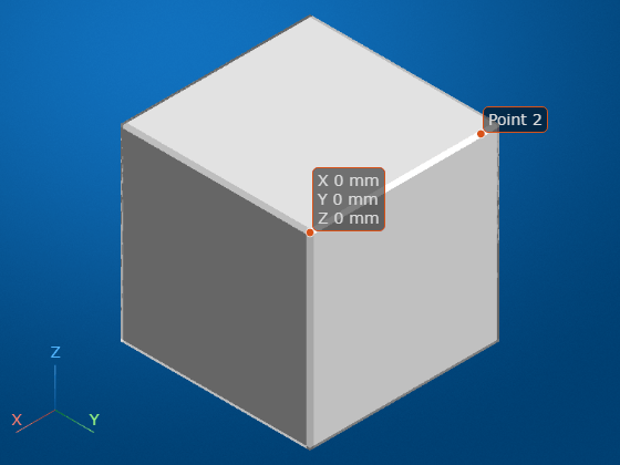
    Create a new viewer window by displaying a 10-by-10-by-10 cube.

    V = ones(10,10,10);
    vol = volshow(V);

    Get a handle to the viewer window that contains the volume.

    viewer = vol.Parent;

    Create a point annotation object with default property values.

    point1 = images.ui.graphics.roi.Point
    point1 = 
      Point with properties:
    
           Label: [0×0 string]
           Color: [0.8500 0.3250 0.0980]
        Position: [0 0 0]
             Tag: ""
        UserData: []


    Create a point annotation with a custom position and label.

    point2 = images.ui.graphics.roi.Point(Position=[1 10 10],Label="Point 2")
    point2 = 
      Point with properties:
    
           Label: "Point 2"
           Color: [0.8500 0.3250 0.0980]
        Position: [1 10 10]
             Tag: ""
        UserData: []


    Add the annotations to the viewer.

    viewer.Annotations = [point1 point2];

    To append spatial units to coordinate labels, update the SpatialUnits property of the viewer. By default, annotation labels do not display a unit.

    viewer.SpatialUnits = "mm";

    Tips

    • The Point object supports these forms of interactivity.

      GoalAction
      Add annotation

      From the Viewer toolstrip, select the point annotation icon Point annotation icon. To place the annotation, click the surface of an object in the viewer.

      Move annotationDrag the vertex of the annotation, not the label. You can reposition the annotation anywhere on the surface of an object in the viewer.
      Edit annotation labelRight-click the vertex of the annotation, not the label. From the context menu, select Edit Label. When the label text highlights, type new text for the label. To finish editing, click outside the label.
      Remove annotationRight-click the vertex of the annotation, not the label. From the context menu, select Remove annotation to remove the selected annotation. Select Remove all annotations to remove all annotations in the viewer.
    • When placing annotations, consider zooming in or snapping to an orthogonal view for greater spatial accuracy. Zoom in using the scroll wheel, or by selecting the zoom icon Zoom icon from the viewer toolstrip. Snap to an orthogonal view by clicking the orientation axes labels in the lower-left corner of the viewer.

    Version History

    Introduced in R2024a

    expand all