Multi-Lidar Calibration
This example shows how to calibrate multiple 3-D lidar sensors mounted on a vehicle to estimate a relative transformation between them. Traditional methods, such as marker-based registration, are difficult when the lidar sensors have a negligible overlap between their fields of view (FOVs). The calibration also becomes more difficult as the number of lidar sensors increases. This example demonstrates the use of the trajectories of individual lidar sensors to estimate the transformation between them. This method of calibration is also known as hand-eye calibration.
The use of multiple lidar sensors on an autonomous vehicle helps to remove blind spots, increases redundancy, and enables high-resolution map creation. To extract meaningful information from multiple lidar sensors, you can fuse the data using the transformation between them. Fusing multiple lidars can be challenging because of variations in resolution between different lidar sensors. This example also demonstrates how to create a high-resolution point cloud map by fusing the point clouds from multiple lidar sensors.
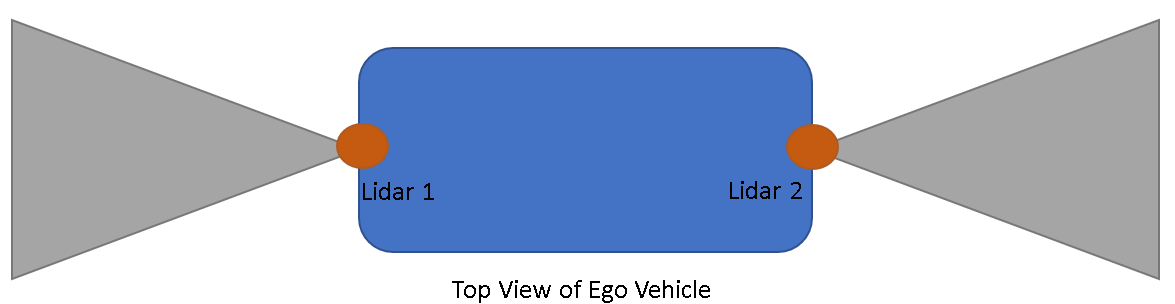
This example uses synthetic input data generated using the Unreal Engine® by Epic Games®. The figure shows the configuration of the sensors mounted on the vehicle.
Load Vehicle Trajectory
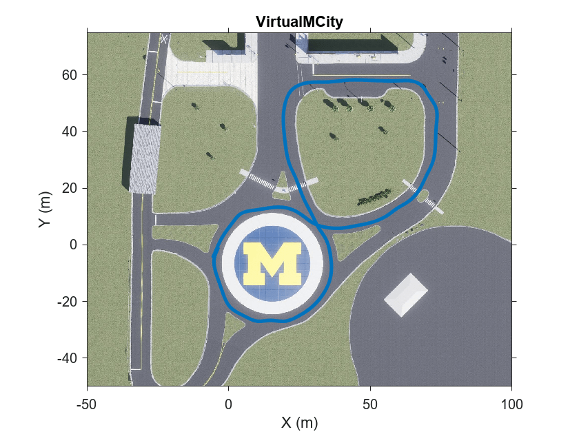
The generated data simulates a vehicle on a predefined trajectory in an urban road setting. For details on how to interactively select a sequence of waypoints from a scene and generate vehicle trajectories, see the Select Waypoints for Unreal Engine Simulation (Automated Driving Toolbox) example. Use the helperShowSceneImage helper function to visualize the path the vehicle follows while collecting the data.
% Load reference path for recorded drive segment
xData = load("refPosesX.mat");
yData = load("refPosesY.mat");
yawData = load("refPosesT.mat");

% Set up workspace variables used by model
refPosesX = xData.refPosesX;
refPosesY = yData.refPosesY;
refPosesT = yawData.refPosesT;

if ismac
    error(['3D Simulation is supported only on Microsoft' char(174) ' Windows' char(174) ' and Linux' char(174) '.']);
end

sceneName = "VirtualMCity";
hScene = figure;
helperShowSceneImage(sceneName)
hold on
scatter(refPosesX(:,2),refPosesY(:,2),7,"filled")

% Adjust axes limits
xlim([-50 100])
ylim([-50 75])
Record Synthetic Data
The MultiLidarSimulation Simulink model is configured for the Virtual Mcity (Automated Driving Toolbox) 3-D environment using the Simulation 3D Scene Configuration (Automated Driving Toolbox) block. A vehicle of type box truck is configured in the scene using the Simulation 3D Vehicle with Ground Following (Automated Driving Toolbox) block. The vehicle has two lidar sensors mounted on it using the Simulation 3D Lidar (Automated Driving Toolbox) block. The two lidars are mounted such that one lidar sensor is mounted at the front bumper and the other at the rear bumper. The mounting position of the lidar sensor can be adjusted using the Mounting tab in the simulation block.
modelName = "MultiLidarSimulation";
open_system(modelName)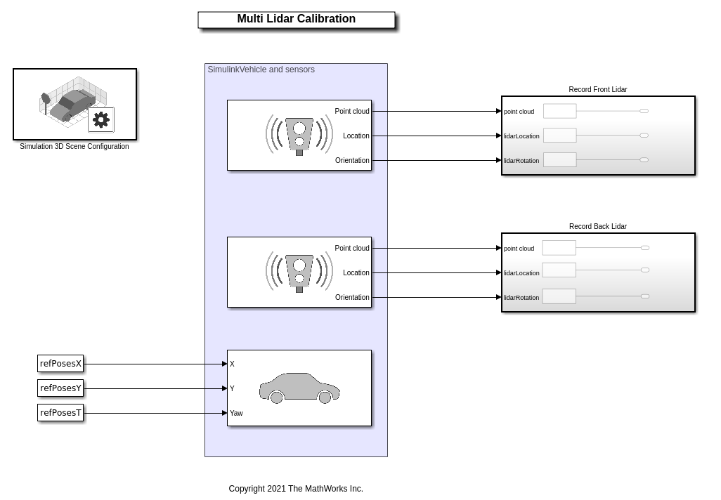
The model records synthetic lidar data and saves it to the workspace.
% Update simulation stop time to end when reference path is completed
simStopTime = refPosesX(end,1);
set_param(gcs,StopTime=num2str(simStopTime));

% Run the simulation
simOut = sim(modelName);
Extract Lidar Odometry
Odometry plays an important role in building a point cloud map. There are several methods to estimate the odometry from lidar data. For this example, use the helperExtractLidarOdometry function to estimate the odometry of the sensors by using the point cloud frames and their absolute poses extracted from simOut. This helper function estimates the odometry by incrementally integrating the relative transformations resulting from consecutive point cloud registrations.
% Front lidar translation and rotation
frontLidarTranslations = simOut.lidarLocation1.signals.values;
frontLidarRotations = simOut.lidarRotation1.signals.values;

% Back lidar translation and rotation
backLidarTranslations = simOut.lidarLocation2.signals.values;
backLidarRotations = simOut.lidarRotation2.signals.values;

% Extract point clouds from the simulation output
[frontLidarPtCloudArr,backLidarPtCloudArr] = helperExtractPointCloud(simOut);

% Extract lidar motion trajectories
frontLidarVset = helperExtractLidarOdometry(frontLidarTranslations,frontLidarRotations, ...
    frontLidarPtCloudArr);
backLidarVset = helperExtractLidarOdometry(backLidarTranslations,backLidarRotations, ...
    backLidarPtCloudArr);
You can further optimize the relative transformation between the frames through loop closure detection. For more details on how to generate a motion trajectory using ICP registration, see the Design Lidar SLAM Algorithm Using Unreal Engine Simulation Environment (Automated Driving Toolbox) example.
The helperVisualizeLidarOdometry helper function visualizes the accumulated point cloud map with the motion trajectory overlaid on it.
% Extract absolute poses of lidar sensor
frontLidarAbsPos = frontLidarVset.Views.AbsolutePose;
backLidarAbsPos  = backLidarVset.Views.AbsolutePose;

% Visualize front lidar point cloud map and trajectory
figure
plot(frontLidarVset)
hold on
plot(backLidarVset)
legend({"Front Lidar Trajectory","Back Lidar Trajectory"})
title("Lidar Trajectory")
view(2)
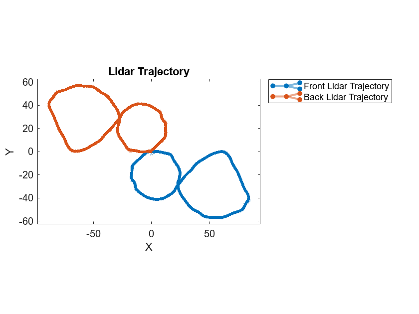
The trajectories of the two lidar sensors appear to be shifted by 180 degrees. This is because the lidar sensors are configured facing in opposite directions in the Simulink model.
Align Lidar Trajectory
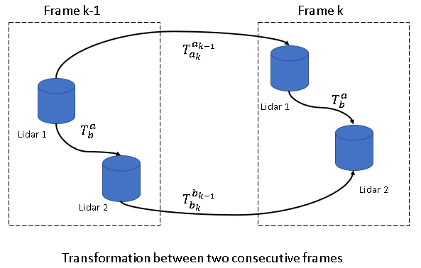
General registration-based methods, using point clouds, often fail to calibrate lidar sensors with nonoverlapping or negligible-overlap fields of view because they lack of sufficient corresponding features. To overcome this challenge, use the motion of the vehicle for registration. Because of the rigid nature of the vehicle and the sensors mounted on it, the motion of each sensor correlates to the relative transformation between the sensors. To extract this relative transformation, formulate the solution to align lidar trajectory as a hand-eye calibration that involves solving the equation , where and are successive poses of the two sensors,and . You can further decompose this equation into its rotation and translation components.
, are the rotation and translation components of sensorfrom timestamp to .,are the rotation and translation components of sensor relative to sensor . This figure shows the relationship between the relative transformation and the successive poses between the two sensors. , is total transformation of sensors and is the relative transformation.
There are multiple ways to solve the equations for rotation and translation[1]. Use the helperEstimateHandEyeTransformation helper function attached as a supporting file to this example, to estimate the initial transformation between the two lidar sensors as a rigidtform3d object. To extract the rotation component of the equation, the function converts the rotation matrices into a quaternion form restructured as a linear system. The function finds the closed-form solution of this linear system using singular value decomposition[2].
tformInit = helperEstimateHandEyeTransformation(backLidarAbsPos,frontLidarAbsPos);
Transformation Refinement
To further refine the transformation, use a registration-based method. Input the translation of each lidar sensor from their respective trajectories to the registration. First, convert the trajectories of the sensors into pointCloud objects. For registration, use the pcregistericp function with the calculated rotation component tformInit as your initial transformation.
% Extract the translation of the front sensor as a point cloud object
frontLidarLocation = vertcat(frontLidarAbsPos.Translation);
frontLidarTrans = pointCloud(frontLidarLocation);

% Extract the translation of the back sensor as a point cloud object
backLidarLocation = vertcat(backLidarAbsPos.Translation);
backLidarTrans = pointCloud(backLidarLocation);

% Register the trajectories of the two sensors
tformRefine = pcregistericp(backLidarTrans,frontLidarTrans,Metric="planeToPlane",InitialTransform=tformInit);
Note that the accuracy of the calibration depends on how accurately you estimate the motion of each sensor. To simplify the computation, the motion estimate for the vehicle assumes the ground plane is flat. Because of this assumption, the estimation loses one degree of freedom along the Z-axis. You can estimate the transformation along the Z-axis by using the ground plane detection method[3]. Use the pcfitplane function to estimate the ground plane from the point clouds of the two lidar sensors. The function estimates the height of each sensor from the detected ground planes of the two lidar sensors. Use the helperExtractPointCloud helper function to extract a pointCloud object array from the simulation output simOut.
% Maximum allowed distance between the ground plane and inliers
maxDist = 0.8;

% Reference vector for ground plane
refVecctor = [0 0 1];

% Fit plane on the a single point cloud frame
frame = 2;
frontPtCloud = frontLidarPtCloudArr(2);
backPtCloud = backLidarPtCloudArr(2);

[~,frontLidarInliers] = pcfitplane(frontPtCloud,maxDist,refVecctor);
[~,backLidarInliers] = pcfitplane(backPtCloud,maxDist,refVecctor);

% Extract relative translation between Z-axis
frontGroundPlane = select(frontPtCloud,frontLidarInliers);
backGroundPlane = select(backPtCloud,backLidarInliers);

frontGroundPts = frontGroundPlane.Location;
backGroundPts = backGroundPlane.Location;

% Compute the difference between mean values of the extracted ground plane
% points
zRel = mean(frontGroundPts(:,3)) - mean(backGroundPts(:,3));

% Update the refined transformation with the estimated relative translation
% in the Z-axis
tformRefine.Translation(3) = zRel;
Fuse Point Cloud
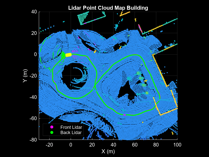
After obtaining the relative transformation between the two lidar sensors, fuse the point clouds from the two lidar sensors. Then fuse the fused point cloud sequentially to create a point cloud map of the data from the two lidar sensors. This figure shows the point cloud fusion method of point cloud map creation.

Use the helperVisualizedFusedPtCloud helper function to fuse the point clouds from the two lidar sensors, overlaid with the fused trajectory after calibration. From the fused point cloud map, you can visually infer the accuracy of the calibration.
helperVisualizedFusedPtCloud(backLidarVset,frontLidarVset,tformRefine)
Results
The accuracy of the calibration is measured with respect to the ground truth transformation obtained from the mounting location of the sensors. The Sport Utility Vehicle (Vehicle Dynamics Blockset) documentation page provides the details of the mounting position of the two lidar sensors. The relative transformation between the two lidar sensors is loaded from the gTruth.mat file.
gt = load("gTruth.mat");
tformGt = gt.gTruth;

% Compute the translation error along the x-, y-, and z-axes
transError = tformRefine.Translation - tformGt.Translation;
fprintf("Translation error along x in meters: %d",transError(1));
Translation error along x in meters: 5.009310e-03
fprintf("Translation error along y in meters: %d",transError(2));Translation error along y in meters: 8.687561e-03
fprintf("Translation error along z in meters: %d",transError(3));Translation error along z in meters: 1.735517e-02
% Compute the rotation error along the x-, y-, and z-axes
quatEstimated = quaternion(tformRefine.R,"rotmat","point");
thetaEstimated = eulerd(quatEstimated,"ZYX","point");

quatGroundTruth = quaternion(tformGt.R,"rotmat","point");
thetaGroundTruth = eulerd(quatGroundTruth,"ZYX","point");

rotError = thetaGroundTruth - thetaEstimated;

fprintf("Rotation error along x in degrees: %d",rotError(3));
Rotation error along x in degrees: -3.706855e-04
fprintf("Rotation error along y in degrees: %d",rotError(2));Rotation error along y in degrees: 3.241185e-05
fprintf("Rotation error along z in degrees: %d",rotError(1));Rotation error along z in degrees: 1.291163e-02
Supporting Functions
helperExtractPointCloud extracts an array of pointCloud objects from a simulation output.
function [ptCloudArr1,ptCloudArr2] = helperExtractPointCloud(simOut)

% Extract signal
ptCloudData1 = simOut.ptCloudData1.signals.values;
ptCloudData2 = simOut.ptCloudData2.signals.values;

numFrames = size(ptCloudData1,4);

% Create a pointCloud array
ptCloudArr1 = pointCloud.empty(0,numFrames);
ptCloudArr2 = pointCloud.empty(0,numFrames);

for n = 1:size(ptCloudData1,4)
    ptCloudArr1(n) = pointCloud(ptCloudData1(:,:,:,n));
    ptCloudArr2(n) = pointCloud(ptCloudData2(:,:,:,n));
end
end
helperExtractLidarOdometry extracts the total transformation of the sensors. This helper function outputs a pcviewset object by adding the point cloud frames with its absolute poses as views, and adding a connection between the successive views by computing the relative transformation between them.
function vSet = helperExtractLidarOdometry(location,theta,ptCloud)

numFrames = size(location, 3);
vSet = pcviewset;
tformRigidAbs = rigidtform3d;
yaw = theta(:,3,1);

% Use first frame as reference frame
tformOrigin = rigidtform3d([0 0 rad2deg(yaw)],location(:,:,1));
vSet = addView(vSet,1,tformRigidAbs,PointCloud=ptCloud(1));
for i = 2:numFrames
    yawCurr = theta(:,3,i);

    transCurr = location(:,:,i);
    tformCurr = rigidtform3d([0 0 rad2deg(yawCurr)],transCurr);

    % Absolute pose
    tformRigidAbs(i) = rigidtform3d(tformOrigin.invert.A * tformCurr.A);
    vSet = addView(vSet,i,tformRigidAbs(i),PointCloud=ptCloud(i));

    % Transform between frame k-1 and k
    relPose = rigidtform3d(tformRigidAbs(i).invert.A * tformRigidAbs(i-1).A);
    vSet = addConnection(vSet,i-1,i,relPose);
end
end
helperVisualizedFusedPtCloud visualizes a point cloud map from the fusion of two lidar sensors.
function helperVisualizedFusedPtCloud(movingVset,baseVset,tform)
hFig = figure(Name="Point Cloud Fusion", ...
    NumberTitle="off");
ax = axes(Parent = hFig);

% Create a scatter object for map points
scatterPtCloudBase = scatter3(ax,NaN,NaN,NaN, ...
    2,"magenta","filled");
hold(ax,"on");
scatterPtCloudMoving = scatter3(ax,NaN,NaN,NaN, ...
    2,"green","filled");
scatterMap = scatter3(ax,NaN,NaN,NaN, ...
    5,"filled");

% Create a scatter object for relative positions
positionMarkerSize = 5;
scatterTrajectoryBase = scatter3(ax,NaN,NaN,NaN, ...
    positionMarkerSize,"magenta","filled");
scatterTrajectoryMoving = scatter3(ax,NaN,NaN,NaN, ...
    positionMarkerSize,"green","filled");
hold(ax,'off');

% Set background color
ax.Color = "k";
ax.Parent.Color = "k";

% Set labels
xlabel(ax,"X (m)")
ylabel(ax,"Y (m)")

% Set grid colors
ax.GridColor = "w";
ax.XColor = "w";
ax.YColor = "w";

% Set aspect ratio for axes
axis(ax,"equal")
xlim(ax, [-30 100]);
ylim(ax, [-80 40]);
title(ax,"Lidar Point Cloud Map Building",Color=[1 1 1])

ptCloudsMoving = movingVset.Views.PointCloud;
absPoseMoving = movingVset.Views.AbsolutePose;

ptCloudsBase = baseVset.Views.PointCloud;
absPoseBase = baseVset.Views.AbsolutePose;

numFrames = numel(ptCloudsMoving);

% Extract relative positions from the absolute poses
relPositionsMoving = arrayfun(@(poseTform) transformPointsForward(poseTform, ...
    [0 0 0]),absPoseMoving,UniformOutput=false);
relPositionsMoving = vertcat(relPositionsMoving{:});

relPositionsBase = arrayfun(@(poseTform) transformPointsForward(poseTform, ...
    [0 0 0]),absPoseBase,UniformOutput=false);
relPositionsBase = vertcat(relPositionsBase{:});

set(scatterTrajectoryBase,"XData",relPositionsMoving(1,1),"YData", ...
    relPositionsMoving(1,2),"ZData",relPositionsMoving(1,3));
set(scatterTrajectoryMoving,"XData",relPositionsBase(1,1),"YData", ...
    relPositionsBase(1,2),"ZData",relPositionsBase(1,3));

% Set legend
legend(ax, {"Front Lidar","Back Lidar"}, ...
    Location="southwest",Color="k",TextColor="w")
skipFrames = 5;
for n = 2:skipFrames:numFrames
    pc1 = pctransform(removeInvalidPoints(ptCloudsMoving(n)),absPoseMoving(n));
    pc2 = pctransform(removeInvalidPoints(ptCloudsBase(n)),absPoseBase(n));
    % Transform moving point cloud to the base
    pc1 = pctransform(pc1,tform);

    % Create a point cloud map and merge point clouds from the sensors
    baseMap = pcalign(ptCloudsBase(1:n),absPoseBase(1:n),1);
    movingMap = pcalign(ptCloudsMoving(1:n),absPoseMoving(1:n),1);

    movingMap = pctransform(movingMap,tform);
    map = pcmerge(baseMap,movingMap,0.1);

    % Transform the position of the moving sensor to the base
    xyzTransformed = [relPositionsMoving(1:n,1),relPositionsMoving(1:n,2), ...
        relPositionsMoving(1:n,3)]*tform.R' + tform.Translation;

    % Plot current point cloud of individual sensor with respect to the ego
    % vehicle
    set(scatterPtCloudBase,"XData",pc2.Location(:,1),"YData", ...
        pc2.Location(:,2),"ZData",pc2.Location(:,3));
    set(scatterPtCloudMoving,"XData",pc1.Location(:,1),"YData", ...
        pc1.Location(:,2),"ZData",pc1.Location(:,3))

    % Plot fused point cloud map
    set(scatterMap,"XData",map.Location(:,1),"YData", ...
        map.Location(:,2),"ZData",map.Location(:,3),"CData",map.Location(:,3));

    % Plot trajectory
    set(scatterTrajectoryBase,"XData",relPositionsBase(1:n,1),"YData", ...
        relPositionsBase(1:n,2),"ZData",relPositionsBase(1:n,3));
    set(scatterTrajectoryMoving,"XData",xyzTransformed(:,1),"YData", ...
        xyzTransformed(:,2),"ZData",xyzTransformed(:,3));

    % Draw ego vehicle assuming the dimensions of a sports utility vehicle
    quat = quaternion(absPoseBase(n).R,"rotmat","point");
    theta = eulerd(quat,"ZYX","point");
    t = xyzTransformed(end,:) + [4.774 0 0]/2*(absPoseBase(n).R');
    pos = [t 4.774 2.167 1.774 theta(2) theta(3) theta(1)];
    showShape("cuboid",pos,Color="yellow",Parent=ax,Opacity=0.9);
    view(ax,2)
    drawnow limitrate
end
end
References
[1] Shah, Mili, Roger D. Eastman, and Tsai Hong. ‘An Overview of Robot-Sensor Calibration Methods for Evaluation of Perception Systems’. In Proceedings of the Workshop on Performance Metrics for Intelligent Systems - PerMIS ’12, 15. College Park, Maryland: ACM Press, 2012. https://doi.org/10.1145/2393091.2393095.
[2] Chou, Jack C. K., and M. Kamel. "Finding the Position and Orientation of a Sensor on a Robot Manipulator Using Quaternions". The International Journal of Robotics Research 10, no. 3 (June 1991): 240–54. https://doi.org/10.1177/027836499101000305.
[3] Jiao, Jianhao, Yang Yu, Qinghai Liao, Haoyang Ye, Rui Fan, and Ming Liu. ‘Automatic Calibration of Multiple 3D LiDARs in Urban Environments’. In 2019 IEEE/RSJ International Conference on Intelligent Robots and Systems (IROS), 15–20. Macau, China: IEEE, 2019. https://doi.org/10.1109/IROS40897.2019.8967797.
Copyright 2021-2025 The MathWorks, Inc.