Connect to Serial Device Using Arduino Explorer App
R2026bThe Arduino Explorer app lets you configure the serial communication interface and read and write data to serial devices connected to Arduino hardware.
Set Up Serial Device
Open the Arduino Explorer app and connect to your Arduino board. In the app, click Serial. In the Set Up Serial Device dialog box, specify which serial port to use and set communication properties.
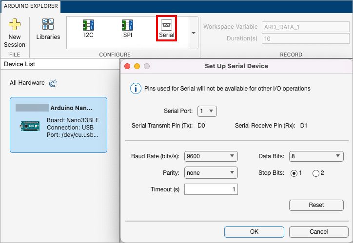
After you set the values, click OK. The Pin Explorer highlights the row specific to the serial pin.
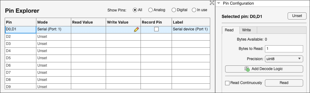
After configuring a serial device, the assigned pins appear in the Pin Explorer with the corresponding serial port label. The Pin Configuration pane provides options to interact with the serial device. You can read incoming data, specify the number of bytes to read, choose the output data type using the Precision setting, and optionally apply custom decode logic to interpret the received data. Use the Write tab to send data to the connected serial device.
Decode Read Data
The Arduino Explorer app lets you decode raw data from the communication protocol interfaces of the board and view the decoded data. In the Pin Explorer pane, select the row corresponding to a communication interface (I2C, SPI or Serial). Then, in the Pin Configuration pane, click Add Decode Logic.
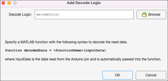
To specify decode logic, you must supply a MATLAB function with this syntax:
function decodedData = functionName(inputData)
Here, inputData is the data read from the Arduino pin, which
the app passes to the function.
To specify this function in the Add Decode Logic window:
If the function is on the MATLAB path, enter the function name in the Decode Logic field.
Otherwise, browse to the location of the function and select it.
Click OK. The Decode Logic field in the Pin Configuration panel updates to show the name of the file.
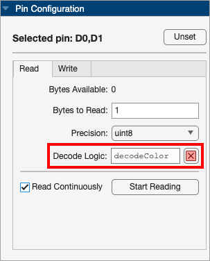
Once you provide the decode logic:
The Read Value column in the Pin Explorer window displays the decoded data instead of raw values from the interface.
The Log pane of the app now displays a new column, Decoded Data, containing the decoded values.
After you configure the serial pins, you can use the app to visualize and record data. For more information, see Visualize and Record Data from Arduino Pins Using Arduino Explorer App.
See Also
Topics
- Set Up and Connect to Arduino and Arduino-compatible Boards Using Arduino Explorer
- Visualize Pin Diagram Using Arduino Explorer App
- Configure Read and Write for GPIO Pins Using Arduino Explorer App
- Connect to SPI Device Using Arduino Explorer App
- Connect to I2C Device Using Arduino Explorer App
- Visualize and Record Data from Arduino Pins Using Arduino Explorer App
- Generate MATLAB Script
- Customizable Views in the App

