Fit Empirical Models to Multi-Injection Diesel Engine Calibration Data
Examine the Test Plans for Point-by-Point Models
After designing the experiments and collecting the data, you can fit statistical models to the data. You can use the toolbox to generate accurate, fast-running models from the measured engine data.
The following graphic shows the models to define in the toolbox to solve this calibration problem. The graphic shows how the model inputs and output relate to the optimal tables, optimization operating points, objectives and constraints you need to perform the optimization and create the calibration.
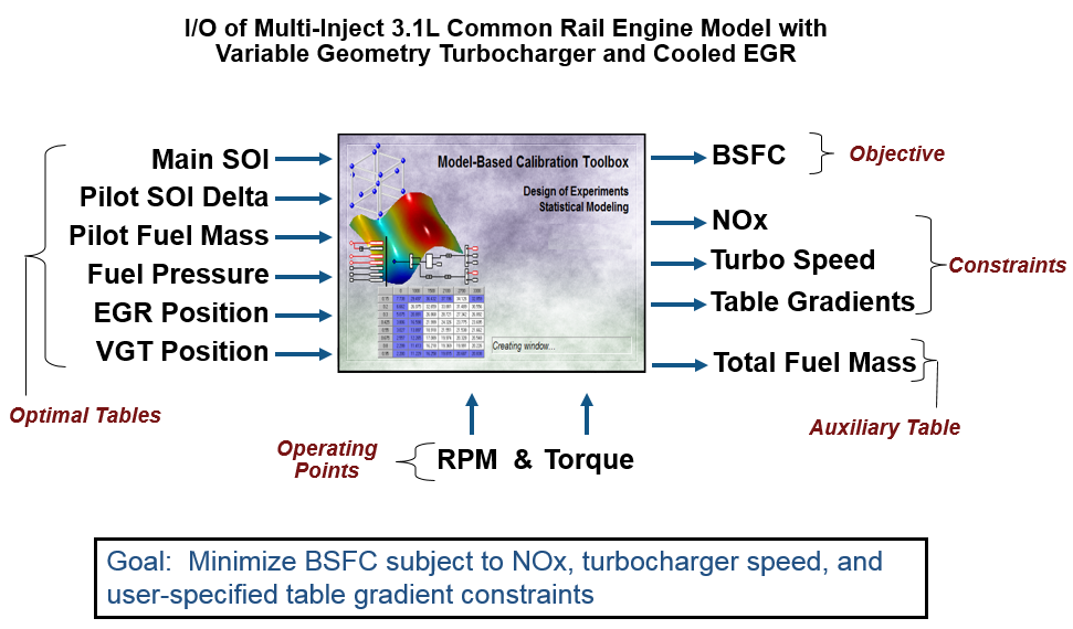
The toolbox provides the data for you to explore this calibration example. For details on how the data was collected, see Data Collection and Physical Modeling.
Examine the model setup.
In MATLAB®, on the Apps tab, in the Automotive group, click MBC Model Fitting.
In the Model Browser home page, in the Case Studies list, select Multi-injection diesel tested with pilot injection on and off. Alternatively, select File > Open Project and browse to the example file
CI_MultiInject_PointbyPoint.mat, found inmatlab\toolbox\mbc\mbctraining.The Model Browser remembers views, so change to the test plan view if necessary, by clicking the
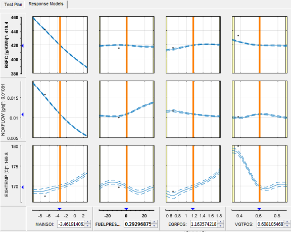
PilotInactivePointbyPointtest plan node in the All Models tree.The Response Models tab shows the cross-section view of the responses. Here you can assess high-level model trends.
Select the Test Plan tab.
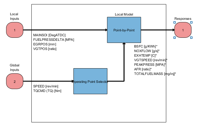
Observe the inputs and response model outputs listed on the test plan diagram. This is a Point-by-Point test plan. The Global Inputs
SPEEDandTQCMDselect the operating points for each model.Double-click the Inputs blocks to view the ranges and names (symbols) for variables on the Input Factor Set Up dialog box.
Double-click the Local Model block to view that the Point-by-Point Model Setup dialog box. View the list of alternative models to fit at each operating point for a point-by-point test plan. When you use the Fit models button in the Common Tasks pane, and select a
Point-by-Pointtemplate, the toolbox selects this list of models. This model setup fits four alternative model types at each operating point, and selects the best model based on the Criteria setting, in this casePRESS RMSE.
Click Cancel to close the Model Setup dialog box without altering your example models.
Similarly, examine the
PilotActivePointbyPointtest plan. This test plan has the same response models and model type setup, but two more local inputs for the pilot injection timing and mass,PILOTDELTASOIandPILOTFMF. The data used to fit the models is also different, with the two additional factors. Observe the Dataset information under the Common Task pane in the test plan view.
For details on setting up point-by-point models, see Fit a Point-by-Point Model.
Examine Response Models
Expand the
PilotInactivePointByPointtest plan node in the All Models tree and select the nodes for each response name, e.g.,BSFC.Click through operating points to see the model selected as best at each point.
The toolbox tries to select the best model for each operating point based on the selected statistical criteria. However, you should always verify the model choices. To search for the best fit you must examine each model, consider removing outliers, and compare with alternative fits. The example models show the results of this process.
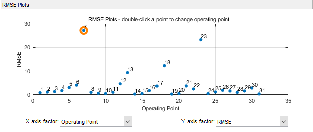
Look at the RMSE Plots. These plots can help you identify problem operating points to investigate. Double-click to view an operating point of interest (with larger RMSE) in the other plots.
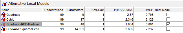
Choose a model to use at a particular operating point by selecting the Best Model check box in the list of Alternative Local Models.
For details on analyzing point-by-point models, see Assess Point-by-Point Models.
For next steps, see Optimize Multi-Injection Diesel Engine Calibration Using Statistical Models.
Tip
Learn how MathWorks® Consulting helps customers develop engine calibrations that optimally balance engine performance, fuel economy, and emissions requirements: see Optimal Engine Calibration.