主要内容

Resonant Voltage Controller

R2026b

Regulate output voltage of a resonant converter using configurable controller gains

Since R2026b

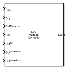
  • Resonant Voltage Controller block icon.

Libraries:
Power Converter Control with Motor Control Blockset / Control / Resonant Converter

Description

The Resonant Voltage Controller block implements a discrete-time voltage controller for LLC resonant converters using direct frequency control. It accepts a voltage reference and measured feedback voltage, and outputs a control variable for the resonant converter using precomputed controller gains from a Resonant Converter Gains block.

Connect the CtrlParams input to the CtrlParams output of a Resonant Converter Gains block configured for your LLC topology and operating point. The gains block populates the ctrltype field of the bus, and the controller uses that field to dispatch between PI, 2P2Z, or 3P3Z controllers. Use the OutUpperLimit and OutLowerLimit ports to clamp the output to the safe operating range of the control variable for your resonant converter. The Rst port resets the integrator state, and OutInit sets the output value at reset.

The block supports three anti-windup options for PI controllers to limit integrator accumulation when the output saturates. Select None for no protection, which is the default. Select Back-calculation to use a feedback path that unwinds the integrator proportionally to the amount of saturation, with a rate controlled by the back-calculation coefficient (Kb) parameter. Select Clamping to stop integration entirely when the output is at a limit.

Examples
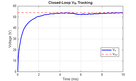
Ports

Input

expand all

Desired output voltage setpoint in volts, specified as a scalar. The block computes the voltage error as this value minus the VFb feedback signal, and drives the control output to reduce that error to zero. Connect this to the output of your voltage reference generator or supervisory controller.

Data Types: single | double

Measured converter output voltage in volts, specified as a scalar. The block subtracts this value from VRef to form the voltage error. Connect this port to a voltage sensor output in your model. Ensure the sensor gain and units match those of the reference signal.

Data Types: single | double

Controller gain parameters bus containing the discrete-time voltage controller gains, specified as a bus. Connect the CtrlParams output of a Resonant Converter Gains block. The bus must contain the following fields:

  • kpvolt — proportional gain for the PI voltage controller

  • kivoltTs — integral gain multiplied by the sample time for the PI voltage controller

  • numecoef — numerator polynomial coefficients of the 2P2Z or 3P3Z compensator

  • dencoef — denominator polynomial coefficients of the 2P2Z or 3P3Z compensator

  • ctrltype — controller type code: 1 for PI, 2 for 2P2Z, 3 for 3P3Z

Data Types: bus

Boolean signal that resets the integrator state when asserted (nonzero), specified as a scalar. When reset occurs, the output is set to the value at x0, which enables bumpless transfer. Use this port to initialize the controller at startup or after a converter fault condition.

Data Types: single | double | Boolean

Initial controller output applied when Rst is asserted, specified as a scalar. The block preloads the integrator state so that the output matches this value immediately after reset, enabling bumpless transfer. Set this to the nominal operating frequency or control variable value at which you want the converter to resume after a reset event.

Data Types: single | double

Maximum allowed numerical value of the controller output, specified as a scalar. The block clamps the output to this value when the controller would otherwise exceed it. For LLC converters where the control variable represents normalized switching frequency, note that a higher numerical output value corresponds to a higher normalized frequency, which is farther above resonance and delivers less power. Set this to the upper bound of the allowed control variable range for your operating region, which typically corresponds to the minimum power (lightest load) operating point.

Data Types: single | double

Minimum allowed numerical value of the controller output, specified as a scalar. The block clamps the output to this value when the controller would otherwise fall below it. For LLC converters where the control variable represents normalized switching frequency, a lower numerical value corresponds to a frequency closer to or below resonance, which delivers more power. Set this to the lower bound of the allowed control variable range, which typically corresponds to the maximum power (full load) operating point and prevents operation below the resonant frequency.

Data Types: single | double

Output

expand all

Controller output clamped to the range [OutLowerLimit, OutUpperLimit], output as a scalar. The block uses the ctrltype field of the CtrlParams bus to select the PI, 2P2Z, or 3P3Z algorithm. Connect this signal to the frequency or control variable input of the resonant converter switching pattern generator.

Data Types: single | double

Parameters

expand all

To edit block parameters interactively, use the Property Inspector. From the Simulink® Toolstrip, on the Simulation tab, in the Prepare gallery, select Property Inspector.

Select None to disable anti-windup protection. Use this option when the output rarely saturates or when the control architecture handles windup externally.

Select Back-calculation to use a feedback path that unwinds the integrator proportionally to the saturation difference. The rate of unwinding is set by the back-calculation coefficient (Kb) parameter. This method provides smooth recovery from saturation events without abruptly stopping integration.

Select Clamping to stop integrating entirely when the output is at a saturation limit. This is the simplest approach to preventing integrator accumulation but may produce a step in the integrator state when the output leaves saturation.

Note

Use anti-windup only when Controller type is set to PI in the Resonant Converter Gains block. For higher-order compensators, set this option to None.

Programmatic Use

To set the block parameter value programmatically, use the set_param function.

Parameter: antiwindup
Values: "None" (default) | "Back-calculation" | "Clamping"

Example: set_param(gcb,"antiwindup","Back-calculation")

Gain for the back-calculation anti-windup loop, specified as a positive scalar. The block uses this value to scale the feedback correction applied to the integrator state when the output saturates. Larger values cause the integrator to unwind faster after saturation. A typical starting value is 1. Increase it if you observe slow recovery after transient events that cause output saturation.

Dependencies

This parameter is visible when Anti-windup Method is set to Back-calculation.

Programmatic Use

To set the block parameter value programmatically, use the set_param function.

To get the block parameter value programmatically, use the get_param function.

Parameter: calcoefficient
Values: "1" (default) | positive scalar in quotes
Data Types: char | string

Example: set_param(gcb,"calcoefficient","2")

Extended Capabilities

expand all

C/C++ Code Generation
Generate C and C++ code using Simulink® Coder™.

Version History

Introduced in R2026b