Sensor Calibration
Compute the Hall sequence and offsets for Hall sensor, quadrature encoder sensor, and ADC to accurately calculate the position and current feedback values.
Featured Examples
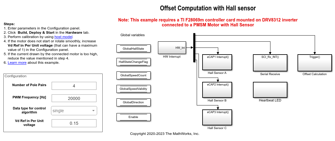
Hall Offset Calibration for PMSM
Calculates the offset between the rotor direct axis (d
-axis) and position detected by the Hall sensor. The field-oriented control (FOC) algorithm needs this position offset to run the permanent magnet synchronous motor (PMSM) correctly. To compute the offset, the target model runs the motor in the open-loop condition. The model uses a constant (voltage along the stator's d
-axis) and a zero (voltage along the stator's q
-axis) to run the motor (at a low constant speed) by using a position or ramp generator. When the position or ramp value reaches zero, the corresponding rotor position is the offset value for the Hall sensors.
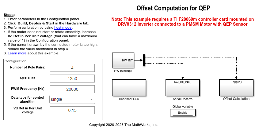
Quadrature Encoder Offset Calibration for PMSM
Calculates the offset between the d
-axis of the rotor and encoder index pulse position as detected by the quadrature encoder sensor. The control algorithm (available in the field-oriented control and parameter estimation examples) uses this offset value to compute an accurate and precise position of the d
-axis of rotor. The controller needs this position to implement the field-oriented control (FOC) correctly in the rotor flux reference frame (d-q reference frame), and therefore, run the permanent magnet synchronous motor (PMSM) correctly.
Run 3-Phase AC Motors in Open-Loop Control and Calibrate ADC Offset
Uses open-loop control (also known as scalar control or Volts/Hz control) to run a motor. This technique varies the stator voltage and frequency to control the rotor speed without using any feedback from the motor. You can use this technique to check the integrity of the hardware connections. A constant speed application of open-loop control uses a fixed-frequency motor power supply. An adjustable speed application of open-loop control needs a variable-frequency power supply to control the rotor speed. To ensure a constant stator magnetic flux, keep the supply voltage amplitude proportional to its frequency.
Hall Sensor Sequence Calibration of BLDC Motor
Calculates the Hall sensor sequence with respect to position zero of the rotor in open-loop control. This workflow helps you to spin the motor using six-step commutation without the need to label the hall sensors or derive the switching sequence. Run this example and obtain the hall sequence, and use this hall sequence with the Six Step Commutation block to run the motor in closed loop as explained in Six-Step Commutation of BLDC Motor Using Sensor Feedback example.
MATLAB Command
You clicked a link that corresponds to this MATLAB command:
Run the command by entering it in the MATLAB Command Window. Web browsers do not support MATLAB commands.
Select a Web Site
Choose a web site to get translated content where available and see local events and offers. Based on your location, we recommend that you select: .
You can also select a web site from the following list
How to Get Best Site Performance
Select the China site (in Chinese or English) for best site performance. Other MathWorks country sites are not optimized for visits from your location.
Americas
- América Latina (Español)
- Canada (English)
- United States (English)
Europe
- Belgium (English)
- Denmark (English)
- Deutschland (Deutsch)
- España (Español)
- Finland (English)
- France (Français)
- Ireland (English)
- Italia (Italiano)
- Luxembourg (English)
- Netherlands (English)
- Norway (English)
- Österreich (Deutsch)
- Portugal (English)
- Sweden (English)
- Switzerland
- United Kingdom (English)
Asia Pacific
- Australia (English)
- India (English)
- New Zealand (English)
- 中国
- 日本Japanese (日本語)
- 한국Korean (한국어)