Verify Stability Margins and Analyze Sensitivity for Non-Isolated DC-DC Converter
R2026bIn this step of the Non-Isolated DC-DC Converter Controller Design Workflow example, you verify stability margins and analyze sensitivity for the non-isolated DC-DC converter. Before deploying the voltage controller, verify that the closed loop remains stable across the full operating envelope. This live script performs classical control analysis for the Buck converter (CCM) voltage loop: it evaluates gain margin, phase margin, and sensitivity peaks at the nominal operating point, and then sweeps load, source voltage, component tolerances, and sampling period to confirm the margins hold under realistic variation.
In this workflow, you:
Compute stability margin metrics at the nominal operating point.
Visualize stability margins and sensitivity functions.
Sweep key parameters (load, voltage, components, control frequency).
Summarize metric variations across operating conditions.
Stability Margins
Converter and Controller Parameterization
The stability and sensitivity analysis requires the converter and controller parameterization data. The "BuckCtrlData.mat" consists default controller parameters and custom controller parameters. Select one of parameterization option from the options listed below.
Parameterization =  "Option1";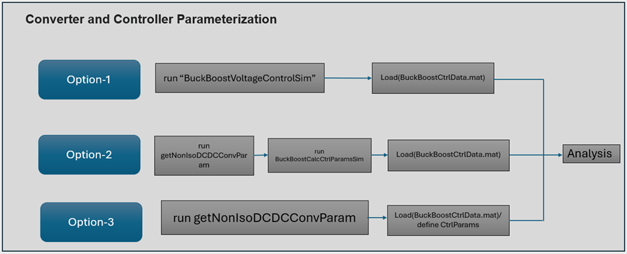
switch (Parameterization)

    case('Option1')
        %Parameterization Option-1

        open_system('BuckVoltageControlSim');
        out = sim('BuckVoltageControlSim','StopTime','0.01');

        saveBuckCtrlData;

        % Controller Data
        load('BuckCtrlData.mat')

        % Default Controller Gains
        CtrlParams.Kp   = BuckCtrlData.Default.Kp; % Kp for PI
        CtrlParams.Ki   = BuckCtrlData.Default.KiTs/Tsc; % Ki for PI
        CtrlParams.K    = BuckCtrlData.Default.KTs/Tsc; % K for type2 compensators
        CtrlParams.T1   = BuckCtrlData.Default.T1; % T1 for type2 compensators
        CtrlParams.T2   = BuckCtrlData.Default.T2; % T2 for type2 compensators
        CtrlParams.Ts   = Tsc; %  Controller Sample time

        if BuckCtrlData.Default.CtrlType == 1
            CtrlParams.Type = 'PI';
        else
            CtrlParams.Type = 'Type2Comp';
        end

    case('Option2')

        %Parameterization Option-2
        NonIsoDCDCConv = getNonIsoDCDCConvParam('Buck20W');
        Tsc = 50e-6;  % Controller Sample time
        Vref = NonIsoDCDCConv.Vout;
        Rload    = NonIsoDCDCConv.Vout/NonIsoDCDCConv.Iout;

        open_system('BuckCalcCtrlParamsSim');
        out = sim('BuckCalcCtrlParamsSim');

        saveBuckCtrlData;

        % Controller Data
        load('BuckCtrlData.mat')

        % Default Controller Parameters
        CtrlParams.Kp   = BuckCtrlData.Default.Kp; % Kp for PI
        CtrlParams.Ki   = BuckCtrlData.Default.KiTs/Tsc; % Ki for PI
        CtrlParams.K    = BuckCtrlData.Default.KTs/Tsc; % K for type2 compensators
        CtrlParams.T1   = BuckCtrlData.Default.T1; % T1 for type2 compensators
        CtrlParams.T2   = BuckCtrlData.Default.T2; % T2 for type2 compensators
        CtrlParams.Ts   = Tsc; %  Controller Sample time

        if BuckCtrlData.Default.CtrlType == 1
            CtrlParams.Type = 'PI';
        else
            CtrlParams.Type = 'Type2Comp';
        end

    case('Option3')

        %Parameterization Option-3
        NonIsoDCDCConv = getNonIsoDCDCConvParam('Buck20W');
        Tsc = 50e-6;  % Controller Sample time

        % Controller Data
        load('BuckCtrlData.mat')

        % Custom Controller Parameters
        CtrlParams.Kp   = BuckCtrlData.Custom.Kp; % Kp for PI
        CtrlParams.Ki   = BuckCtrlData.Custom.KiTs/Tsc; % Ki for PI
        CtrlParams.K    = BuckCtrlData.Custom.KTs/Tsc; % K for type2 compensators
        CtrlParams.T1   = BuckCtrlData.Custom.T1; % T1 for type2 compensators
        CtrlParams.T2   = BuckCtrlData.Custom.T2; % T2 for type2 compensators
        CtrlParams.Ts   = Tsc; %  Controller Sample time

        if BuckCtrlData.Custom.CtrlType == 1
            CtrlParams.Type = 'PI';
        else
            CtrlParams.Type = 'Type2Comp';
        end
end
Saved Controller default values to "BuckCtrlData.mat"
Analyze Stability (Nominal Operating Point)
Evaluate the stability margin metrics at the nominal operating point using the analytical plant model. This establishes reference values for gain margin, phase margin, crossover frequency, and sensitivity peaks.
results = BuckClassicalSensitivity('TF', CtrlParams, BuckConv=NonIsoDCDCConv);Using Open-Loop Bode
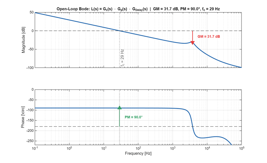
The open-loop transfer function yields two classical stability margins:
Phase Margin (PM) = — additional phase lag tolerable at the gain crossover frequency
Gain Margin (GM) = dB — additional plant gain tolerable at the phase crossover frequency
SensitivityPlots(results, plots='bode', Visible='on');
Using Sensitivity Functions
While GM and PM are widely used, they are single-point metrics evaluated at specific frequencies. They do not reveal:
How close the Nyquist curve passes to the critical point at intermediate frequencies between and .
The worst-case amplification of disturbances or plant uncertainty across the entire frequency range.
Whether a system with acceptable GM and PM might still exhibit excessive peaking (poor damping or near-instability at some frequency)
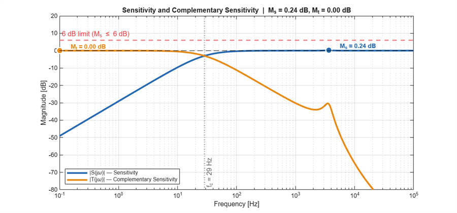
The sensitivity function quantifies how much the feedback loop attenuates or amplifies disturbances at the output.
The complementary sensitivity function describes how well the closed-loop system tracks the reference input.
Frequency Response Analysis of and
(Sensitivity magnitude): At each frequency, equals the factor by which output disturbances are amplified (or attenuated) by the feedback loop.
(negative dB): The loop rejects disturbances at that frequency (good).
(positive dB): The loop amplifies disturbances at that frequency (undesirable).
(0 dB): No benefit from feedback.
(Complementary Sensitivity magnitude): At each frequency, equals the factor by which sensor noise propagates to the output.
at low frequencies: Good reference tracking.
: Noise amplification and potential instability.
at high frequencies: Noise is rejected.
— disturbance-to-output transfer. Peak quantifies worst-case disturbance amplification. (6 dB) guarantees GM 6 dB and PM .
— reference-to-output transfer. Peak indicates closed-loop resonance; implies overshoot .
These satisfy : improving one at any frequency necessarily limits the other.
SensitivityPlots(results, plots='sensitivity', Visible='on');
Using Time-domain Step Response
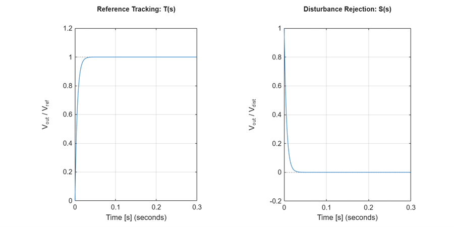
The time-domain step response complements the frequency-domain analysis by revealing transient behavior directly.
Reference Tracking T(s)
A unit step is applied at and the normalized output is observed.
Shows how quickly and accurately the output voltage follows a reference change.
Look for: rise time (speed), overshoot (damping), and settling time (stability).
A well-tuned controller reaches the target quickly with minimal overshoot.
Disturbance Rejection S(s)
A unit step disturbance is injected at the output and is observed.
Shows how effectively the controller suppresses load transients.
Peak value indicates worst-case output deviation; settling time indicates recovery speed.
Ideally this response decays to zero rapidly.
SensitivityPlots(results, plots='step', Visible='on');
Metrics Summary
The horizontal bar indicators below consolidate all stability and sensitivity metrics at the nominal operating point. Each metric is evaluated against three zones: excellent (green), acceptable (yellow), and insufficient (red). A robust design requires all five metrics within the acceptable or excellent region.
MetricsDashboard(results, Visible='on');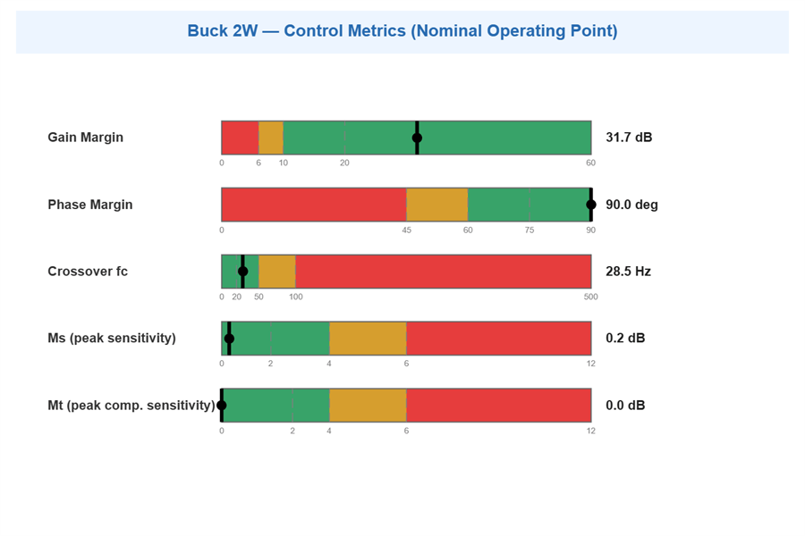
Nominal Operating Point Summary
Tabulated margins and sensitivity peaks with assessment.
SensitivityPrintResults(results);
╔══════════════════════════════════════════════════════════════╗
║        BUCK CLASSICAL SENSITIVITY ANALYSIS RESULTS            ║
╠══════════════════════════════════════════════════════════════╣
║  Converter: 2W  |  Method: TF      |  Controller: PI       ║
╚══════════════════════════════════════════════════════════════╝

┌────────────────────────────────────────────────────────────┐
│              KEY METRICS AT A GLANCE                       │
├──────────────────┬────────────────┬────────────────────────┤
│ Metric           │ Value          │ Assessment             │
├──────────────────┼────────────────┼────────────────────────┤
│ Crossover fc     │ 28.5 Hz        │ [OK ] Good            │
│ Phase Margin     │ 90.0 deg       │ [OK ] Excellent       │
│ Gain Margin      │ 31.7 dB        │ [OK ] Excellent       │
│ Ms (peak |S|)    │ 0.24 dB        │ [OK ] Very robust     │
│ Mt (peak |T|)    │ 0.00 dB        │ [OK ] No resonance    │
│ Rise Time        │ 12 ms          │ [~  ] Slow            │
└──────────────────┴────────────────┴───────────────────────┘

┌──────────────────────────────────────────────────────────────────────────┐
│                        DETAILED RESULTS                                  │
├────────────┬──────────────────┬────────────────────┬─────────────────────┤
│ Category   │ Parameter        │ Value              │ Assessment          │
├────────────┼──────────────────┼────────────────────┼─────────────────────┤
│ Plant      │ Kdc (Vin)        │ 9.00 V             │ [OK ] Normal        │
│            │ LC pole fp       │ 3650.5 Hz          │                     │
│            │ ESR zero fz      │ 13.4 kHz           │                     │
│            │ Switching freq   │ 200.00 kHz         │                     │
│            │ D = Vout/Vin     │ 0.44               │ [OK ] Normal        │
├────────────┼──────────────────┼────────────────────┼─────────────────────┤
│ Controller │ Type             │ PI                 │                     │
├────────────┼──────────────────┼────────────────────┼─────────────────────┤
│ Stability  │ Crossover fc     │ 28.52 Hz           │ [OK ] Good          │
│            │ Phase Margin     │ 90.0 deg           │ [OK ] Excellent     │
│            │ Gain Margin      │ 31.7 dB (x39)      │ [OK ] Excellent     │
│            │ Ms               │ 1.0285 (0.24 dB)   │ [OK ] Very robust   │
│            │ Ms frequency     │ 3631.4 Hz          │                     │
├────────────┼──────────────────┼────────────────────┼─────────────────────┤
│ Performance │ Rise time        │ 12 ms              │ [~  ] Slow          │
│            │ Disturbance BW   │ ~29 Hz             │ [OK ] Good          │
│            │ Overshoot        │ 0%                 │ [OK ] Excellent     │
└────────────┴──────────────────┴────────────────────┴─────────────────────┘

┌────────────────────────────────────────────────────────────┐
│              ROBUSTNESS CLASSIFICATION                     │
├────────────────────────────────────────────────────────────┤
│  [***] Ms < 1.6 dB : VERY ROBUST                         │
│        Guaranteed: GM > 10 dB, PM > 50 deg                │
├────────────────────────────────────────────────────────────┤
│  Scale:  [***] Very Robust  [** ] Robust                  │
│          [*  ] Acceptable   [!  ] Fragile                 │
└────────────────────────────────────────────────────────────┘

───────────────────────────────────────────────────────────────
  Stability: EXCELLENT  |  Performance: POOR (fc=29 Hz)
───────────────────────────────────────────────────────────────
Analyze Robustness (Parametric Sweeps)
This Section describes stability metrics variation w.r.t parameter sweep.
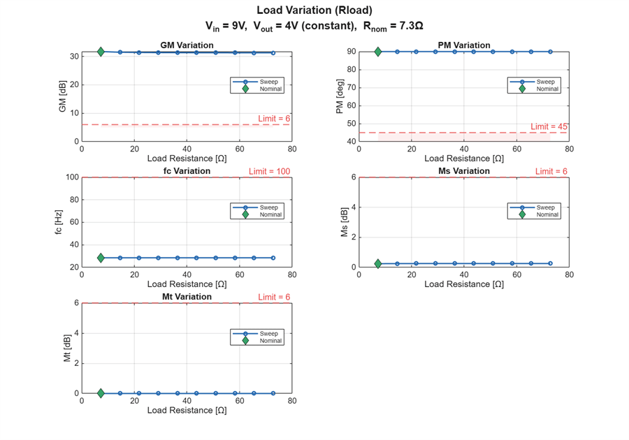
Load Variation (10% to 100% rated power)
Sweep load resistance from nominal (full load) to nominal (10% load). As increases, the converter operates at lighter loads, shifting the plant pole and gain.
Constant: , , controller parameters, , L, C
Varies: decreases with increasing resistance
Rnom = NonIsoDCDCConv.Vout^2 / NonIsoDCDCConv.Pout;
RloadRange = linspace(Rnom, 10*Rnom, 10)';

[sweepRload, ~] = ParametricSweep(NonIsoDCDCConv, CtrlParams, ...
    SweepParam='Rload', Range=RloadRange, Visible='on');
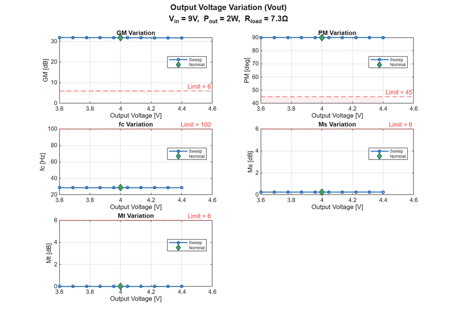
Output Voltage Variation (Vout +/- 10%)
Sweep .
Constant: , , controller gains, , L, C
Varies: changes with output voltage
VoutRange = linspace(0.9*NonIsoDCDCConv.Vout, 1.1*NonIsoDCDCConv.Vout, 10)';

[sweepVout, ~] = ParametricSweep(NonIsoDCDCConv, CtrlParams, ...
    SweepParam='Vout', Range=VoutRange, Visible='on');
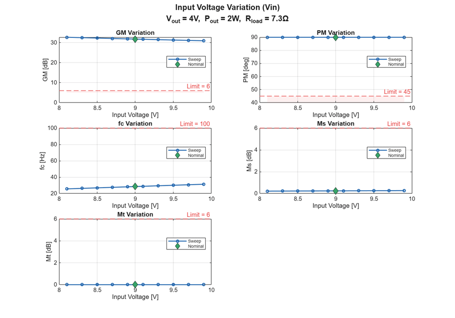
Input Voltage Variation (Vin +/- 10%)
Sweep .
Constant: , , controller gains, , L, C
Varies:
VinRange = linspace(0.9*NonIsoDCDCConv.Vin, 1.1*NonIsoDCDCConv.Vin, 10)';

[sweepVin, ~] = ParametricSweep(NonIsoDCDCConv, CtrlParams, ...
    SweepParam='Vin', Range=VinRange, Visible='on');
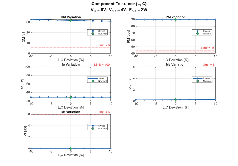
Component Tolerance (L, C +/- 10%)
Sweep inductor and capacitor together by percentage deviation.
Constant: , , , controller gains,
Varies: L, C, quality factor
LCRange = linspace(-10, 10, 10)';

[sweepLC, ~] = ParametricSweep(NonIsoDCDCConv, CtrlParams, ...
    SweepParam='LC', Range=LCRange, Visible='on');
Control Frequency Variation (20% to 200% rated)
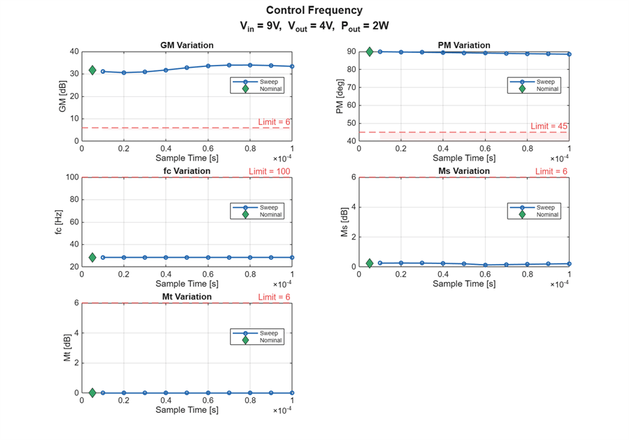
Sweep sampling period from 10 s to 100 s. The digital delay erodes phase margin as control frequency decreases.
Constant: , , , controller gains, L, C
Varies: PWM delay magnitude — longer adds more phase lag at crossover
TsRange = linspace(10e-6, 100e-6, 10)';

[sweepTs, ~] = ParametricSweep(NonIsoDCDCConv, CtrlParams, ...
    SweepParam='Ts', Range=TsRange, Visible='on');
Sensitivity Matrix
Summary showing min/max of each metric across all sweeps with overall pass/fail verdict.
sweeps = {sweepRload, sweepVout, sweepVin, sweepLC, sweepTs};
labels = {'Rload (1x-10x)', 'Vout +/-10%', 'Vin +/-10%', 'L,C +/-10%', 'Ts (10-100us)'};

lim = MetricsLimits();
passCriteria = struct('GMmin', lim.GM.pass, 'PMmin', lim.PM.pass, ...
    'fcMin', lim.fc.pass, 'MsMax', lim.Ms.pass);

fprintf('\n');
fprintf('================================================================\n');
================================================================
fprintf(' SENSITIVITY MATRIX - Buck %.0fW Synchronous\n', NonIsoDCDCConv.Pout);SENSITIVITY MATRIX - Buck 2W Synchronous
fprintf('================================================================\n');================================================================
fprintf('  %-17s | %12s | %12s | %12s | %12s | %s\n', ...
    'Variation', 'GM [dB]', 'PM [deg]', 'fc [Hz]', 'Ms [dB]', 'Pass');
Variation | GM [dB] | PM [deg] | fc [Hz] | Ms [dB] | Pass
fprintf('  %-17s | %12s | %12s | %12s | %12s |\n', ...
    '', 'min / max', 'min / max', 'min / max', 'min / max');
| min / max | min / max | min / max | min / max |
fprintf('----------------------------------------------------------------\n');----------------------------------------------------------------
allPass = true;
for i = 1:5
    sw = sweeps{i};
    gmMin = min(sw.GM(~isnan(sw.GM)));
    gmMax = max(sw.GM(~isnan(sw.GM)));
    pmMin = min(sw.PM(~isnan(sw.PM)));
    pmMax = max(sw.PM(~isnan(sw.PM)));
    fcMin = min(sw.fc(~isnan(sw.fc)));
    fcMax = max(sw.fc(~isnan(sw.fc)));
    msMin = min(sw.Ms(~isnan(sw.Ms)));
    msMax = max(sw.Ms(~isnan(sw.Ms)));

    rowPass = (gmMin >= passCriteria.GMmin) && ...
        (pmMin >= passCriteria.PMmin) && ...
        (fcMin >= passCriteria.fcMin) && ...
        (msMax <= passCriteria.MsMax);

    if rowPass
        passStr = ' OK';
    else
        passStr = 'FAIL';
        allPass = false;
    end

    fprintf('  %-17s | %5.1f / %-5.1f | %5.1f / %-5.1f | %5.0f / %-5.0f | %5.2f / %-5.2f | %s\n', ...
        labels{i}, gmMin, gmMax, pmMin, pmMax, fcMin, fcMax, msMin, msMax, passStr);
end
  Rload (1x-10x)    |  31.3 / 31.7  |  90.0 / 90.0  |    29 / 29    |  0.24 / 0.26  | FAIL
  Vout +/-10%       |  31.6 / 31.8  |  90.0 / 90.0  |    29 / 29    |  0.24 / 0.25  | FAIL
  Vin +/-10%        |  30.9 / 32.6  |  90.0 / 90.0  |    26 / 31    |  0.22 / 0.27  | FAIL
  L,C +/-10%        |  30.9 / 32.6  |  90.0 / 90.0  |    29 / 29    |  0.22 / 0.27  | FAIL
  Ts (10-100us)     |  30.6 / 34.0  |  88.5 / 89.9  |    29 / 29    |  0.14 / 0.26  | FAIL
fprintf('----------------------------------------------------------------\n');----------------------------------------------------------------
fprintf('  Limits:    |    >= %-6g |    >= %-6g |    >= %-6g |    <= %-6g |\n', ...
    passCriteria.GMmin, passCriteria.PMmin, passCriteria.fcMin, passCriteria.MsMax);
Limits: | >= 6 | >= 45 | >= 100 | <= 6 |
fprintf('================================================================\n\n');================================================================
fprintf('  Nominal: GM=%.1f dB, PM=%.1f deg, fc=%.1f Hz, Ms=%.2f dB\n', ...
    sweepRload.nominal.GM, sweepRload.nominal.PM, sweepRload.nominal.fc, sweepRload.nominal.Ms);
Nominal: GM=31.7 dB, PM=90.0 deg, fc=28.5 Hz, Ms=0.24 dB

