Estimate Online Frequency Response of PFC Boost Converter
R2026bIn this step of the PFC Boost Converter Controller Design Workflow example, you estimate the online frequency response of the PFC boost converter plant to obtain a data-driven model for inner current-loop tuning. To get started, open the project and click the FRE Workflow shortcut on the project toolstrip.
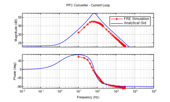
This workflow extracts the duty-cycle-to-inductor-current frequency response of the PFC boost converter under open-loop control. The AC source is replaced with a DC source to fix the operating point, both PI controllers are deactivated to open the loop, and a sinestream perturbation is injected on the duty cycle. A well-conditioned frequency response estimation (FRE) result gives you a data-driven plant model that captures effects the analytical transfer function misses, including parasitic resistances, quantization, and digital sampling dynamics.
The FRE workflow is supported for the Classical topology. The model and plant parameters are loaded from PFCPlantParameters.m.
Configure FRE Injection Parameters
% Select the PFC converter topology
PFCConfig = 'Classical'; % Totempole is not supoprted for FRE workflow

% Get the parameters as per the selected topology
PFCConv = PFCPlantParameters(PFCConfig);

Ts       = 1/PFCConv.fsw;       % Current controller sample time [s]
TsVolt   = Ts * 50;             % Voltage controller sample time [s]
TsPlant  = 1/(50*PFCConv.fsw);  % Converter sample time for simulation [s]
Define series of frequencies to be injected
D_op         = 0.5;  % Open loop duty cycle
freq         = [10:10:200, 300:100:3000];% Hz
Amplitudes   = 0.02; % Duty cycle, use higher value ~0.1 for totempole
NumSetPeriod = 5;    % Number of settling periods for the frequency injection
NumEstPeriod = 3;    % Number of estimation periods for the frequency injection

% Calculate simulation time to inject the frequencies
TestTime = 0;
for index = 1:length(freq)
    TestTime = TestTime + (NumSetPeriod+NumEstPeriod) / freq(index);
end
TestTime = TestTime*1.01;
Simulate FRE Model
Run simulation
modelName   = 'OnlineFRESim';
FreStartTime = 0.2;
SimTime1     = TestTime + FreStartTime;
open_system(modelName);
Simulate the model
sim(modelName);
Plot the Frequency Response and compare against Transfer Function (including parasites)
opts=bodeoptions;
opts.FreqUnits='Hz';
opts.Grid='On';
opts.MagVisible ='On';
opts.PhaseVisible ='On';

pfcfreSim = frd(FRD.Data, freq * 2 * pi);
rootFolder = currentProject().RootFolder;
save (rootFolder+'\Data\pfcfreSim.mat',"pfcfreSim"); clear rootFolder;
Analytical duty-to-inductor-current transfer function
Vin  = PFCConv.VIn;
Rl   = PFCConv.Rload;
L    = PFCConv.LBoost;
C    = PFCConv.CBoost;
Dp   = 1-D_op;
Vout = PFCConv.VInPeak/(1-Dp);
RL_dcr = 0.01 + 2*0.3;  % Resistance of boost inductor and rectifier diodes
Rc     = 1e-6;          % Resistance of boost capacitor
s = tf('s');
num = Vout*(1 + s*C*(Rl+Rc));
den = s^2*L*C*(Rl+Rc) + s*(L + C*(RL_dcr*(Rl+Rc) + Rc*Rl*Dp^2)) + RL_dcr + Dp^2*Rl;
Gid = num/den;
figure('Name','FRE plot')
bodeplot(pfcfreSim,'r*-',Gid,'b-',opts);
legend('FRE Simulation','Analytical Gid');
title('PFC Converter - Current Loop');