PFC Boost Converter Controller Design Workflow
R2026bPower Factor Correction Controller Design Workflow
This project walks through the end-to-end workflow for designing and validating a cascaded current and voltage controller for a Power Factor Correction (PFC) boost converter, starting from a set of converter parameters and ending with a controller that is validated in simulation and robust across the operating envelope.
The workflow is arranged in three stages: model configuration and closed-loop simulation, online frequency response estimation (FRE), and stability and sensitivity analysis. These stages share a common set of parameters and gains that flow through subsystem references and MAT-file data stores, so a single edit in the plant or controller definition propagates automatically into every downstream stage.
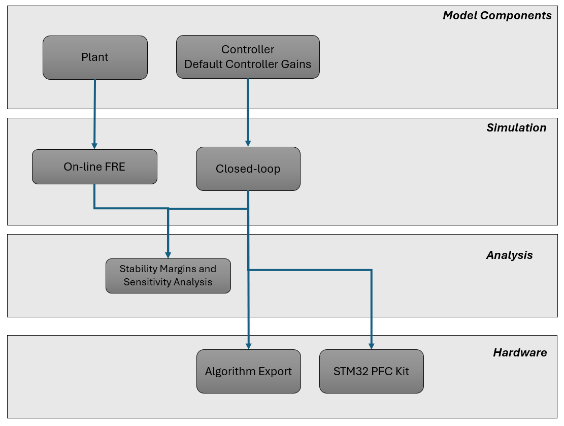
PFC Control Design Steps
Each stage is a separate live script, accessible from a project shortcut on the MATLAB® toolstrip. The example series consists of these steps:
Configure and Simulate PFC Boost Converter Controller
Estimate Online Frequency Response of PFC Boost Converter
Verify Stability Margins and Analyze Sensitivity for PFC Boost Converter
Open the PFC Boost Converter Project
The PFCExample.prj project file contains the reference application, which consists of the Simscape™ Electrical™ plant subsystem reference, the current and voltage controller subsystem references, the ctrlData.mat gains data store, all supporting utilities, and the toolstrip project shortcuts that open the live script for each stage of this workflow. Open the project file by running this code.
prj = openProject("PFCWorkflow");Open the SimulateBoostPFC.slx Simulink(R) model.
open_system("SimulateBoostPFC");The SimulateBoostPFC.slx model is the entry point for the closed-loop desktop simulation and contains the following top-level components, which you can customize in accordance with your design:
PFC boost converter plant. Subsystem reference that models the power stage of either the Classical or Totem-Pole boost topology using Simscape Electrical. The active topology is selected through the
PFCConfigproperty.Current controller. Subsystem reference that implements the inner current control loop of the proportional-integral (PI) cascaded controller.
Voltage controller. Subsystem reference that implements the outer voltage control loop of the PI cascaded controller.
Controller gains data store.
ctrlData.matin~\Data\stores the default gains produced by the analytical design and any custom gains tuned by hand or refined through online FRE, so every downstream stage reads from the same file.Project shortcuts. Toolstrip buttons that open the live script for each stage of the workflow, along with supporting shortcuts for parameterization and post-processing.

For the first stage of the workflow, which configures the converter parameters and controller gains and runs the closed-loop simulation, click the Configure and Simulate project shortcut.
Workflow Steps
To learn more about each step in the workflow, see:

