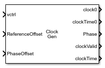
Clock Generator
Libraries:
Mixed-Signal Blockset /
Utilities
Description
The Clock Generator block generates a clock signal with multiple output phases and detailed phase noise modeling. The signals at two output ports together model the output clock signal for each phase. These signals are: a saturated clock signal at the clock port and a clock transition time at the clockTime port.
You can use the block to model any clock recovery loop that uses a voltage controlled oscillator (VCO). The block consistently provides clock times where the noise floor is below –150 dBC/Hz. You can also use the block to include phase noise that matches a physical model.
Ports
Input
Voltage to control the output frequency, specified as a scalar or vector.
Data Types: double
Offset for the reference frequency, specified as a scalar. If you select the ReferenceOffsetPort parameter, the ReferenceOffset port uses a reference offset value from an external block.
Data Types: double
Offset for the duty cycle phase offset, specified as a scalar. If you select the PhaseOffsetPort parameter, the PhaseOffset port uses a phase offset value from an external block.
Data Types: double
Output
Saturated output clock signal, returned as a scalar. There is one clock output port for each output phase.
clock0 is the default name of the port. The nonnegative scalar that follows the port name clock indicates the clock phase. For example, clock1 represents the saturated output clock signal for phase 1.
The output is a square wave whose amplitude is defined by the Output amplitude parameter.
Data Types: double
Simulation time at the last clock transition, returned as a scalar. There is one clockTime output port for each output phase.
clockTime0 is the default name of the port. The nonnegative scalar that follows the port name clockTime indicates the clock phase. For example, clockTime1 represents the clock transition time for phase 1.
Data Types: double
Most recent clock phase of the fundamental clock, returned as a scalar.
Data Types: double
Variable-step discrete-sampled clock, specified as a scalar. The edge sample times of the signal at the clockValid port exactly match the values in the clock time signal.
Data Types: double
Absolute clock time of the most recent clock change at the clockValid port.
Data Types: double
Parameters
Main
Define control sensitivity of theclock generator.
Select
Voltage sensitivityto specify output frequency from the Voltage sensitivity (Hz/V) and Free running frequency (Hz) parameters.Select
Output frequency vs. control voltageto interpolate output frequency from the Control voltage (V) vector versus the Output frequency (Hz) vector.Select
Period offsetto adjust the cycle time by the fraction of a nominal clock period. Use the Control voltage (V) parameter to specify the fraction. The block determines the values of the Voltage sensitivity (Hz/V) and Free running frequency (Hz) parameters using the value set in the Symbol time (s) parameter.
Programmatic Use
Block parameter:
SpecifyUsing |
| Type: character vector |
Values:
Voltage sensitivity | Output frequency vs.
control voltage | Period offset |
Default:
Voltage sensitivity |
Measure of change in output frequency for input voltage change, specified as a positive real scalar with units in Hz/V.
Programmatic Use
Block parameter:
Kvco |
| Type: character vector |
| Values: positive real scalar |
Default:
100e6 |
Data Types: double
Frequency of the clock generator without any control voltage input
(0 V) or the quiescent frequency, specified as a positive real
scalar in hertz.
Programmatic Use
Block parameter:
Fo |
| Type: character vector |
| Values: positive real scalar |
Default:
10e9 |
Data Types: double
Control voltage values of the clock generator, specified as a real valued vector in volts.
Programmatic Use
Block parameter:
ControlVoltage |
| Type: character vector |
| Values: real valued vector |
Default:
[-5 0 5] |
Data Types: double
Output frequency of the clock generator corresponding to the Control voltage (V) vector, specified in hertz.
Programmatic Use
Block parameter:
OutputFrequency |
| Type: character vector |
| Values: positive real valued vector |
Default:
[9.9e9 10e9 10.5e9] |
Data Types: double
Maximum amplitude of the clock generator output voltage, specified as a positive real scalar.
Programmatic Use
Block parameter:
Amplitude |
| Type: character vector |
| Values: positive real scalar |
Default:
1 |
Data Types: double
The units of the output phase and duty cycle, specified as
Degrees or Fraction of a clock
cycle.
Programmatic Use
Block parameter:
PhaseUnits |
| Type: character vector |
Values:
Degrees | Fraction of a clock
cycle |
Default:
Degrees |
The phases of the output clock signals, specified as a scalar vector. If specified as a vector, each element defines one output.
Programmatic Use
Block parameter:
OutputPhase |
| Type: character vector |
| Values: nonnegative real scalar | nonnegative real valued vector |
Default:
[0] |
The duty cycles of the output clock signals, specified as a scalar or a vector. The clock output phase refers to the rising edge of the output clock.
If specified as a vector, each element defines one output. Missing or empty elements of the vector are given the default duty cycle. Extra elements are ignored.
The duty cycle must be greater than but less than , defined as a fraction of clock cycle.
Programmatic Use
Block parameter:
OutputDutyCycle |
| Type: character vector |
| Values: positive real scalar | positive real valued vector |
Default:
[180] |
Define the duty cycle phase offset through PhaseOffset input port from an external block. If you deselect the PhaseOffsetPort parameter, it is removed from the AMI files. This effectively hard-codes phase offset to the value defined by the Phase offset (symbol time) parameter.
Duty cycle phase offset, specified as a scalar in the range [-0.5, 0.5] in fraction of symbol time. Phase offset manually shifts clock probability distribution function (PDF) for better bit error rate (BER)..
Dependencies
To enable this parameter, deselect PhaseOffsetPort.
Programmatic Use
Block parameter:
PhaseOffset |
| Type: character vector |
| Values: scalar |
Default:
0 |
Define the reference frequency offset through ReferenceOffset input port from an external block. If you deselect the ReferenceOffsetPort parameter, it is removed from the AMI files. This effectively hard-codes Reference offset to the value defined by the Reference clock frequency offset (ppm) parameter.
The factor by which the nominal output frequency is to be offset from , specified as a scalar in the range of [-300,300] in unit of parts per million. It is the deviation between the transmitter oscillator frequency and the receiver oscillator frequency
Dependencies
To enable this parameter, deselect ReferenceOffsetPort.
Programmatic Use
Block parameter:
ReferenceOffset |
| Type: character vector |
| Values: scalar in the range of [-300,300] |
Default:
0 |
Select the simulation mode. This choice affects the simulation performance.
Simulating the model using the Code generation method
requires additional startup time, but the subsequent simulations run faster. Simulating
the model using the Interpreted execution method may reduce
the startup time, but the subsequent simulations run slower. For more information, see
Interpreted Execution vs. Code Generation.
Programmatic Use
Block parameter:
SimulateUsing |
| Type: character vector |
Values:
Code generation| Interpreted
execution |
Default:
Code generation |
Phase Noise
Select to introduce phase noise as a function of frequency. By default, this option is selected.
The frequency offsets of the specified phase noise from the carrier frequency, specified as a positive real valued vector in hertz.
Dependencies
To enable this parameter, select Add phase noise in the Impairments tab.
Programmatic Use
Block parameter:
Foffset |
| Type: character vector |
| Values: positive real valued vector |
Default:
[30e3 100e3 1e6 3e6 10e6] |
Data Types: double
The specified phase noise power in a 1 Hz bandwidth centered at the phase noise frequency offsets relative to the carrier, specified as a negative real valued vector in dBc/Hz. The elements of Phase noise level correspond to relative elements in the Phase noise frequency offset (Hz) parameter.
Dependencies
To enable this parameter, select Add phase noise in the Impairments tab.
Programmatic Use
Block parameter:
PhaseNoise |
| Type: character vector |
| Values: negative real valued vector |
Default:
[-56 -106 -132 -143 -152] |
Data Types: double
Click to estimate the phase noise parameters from the phase noise measured phase noise data. This calculates the Period jitter (S) and Flicker corner frequency (Hz) parameters from the Phase noise frequency offset (Hz) and Phase noise level (dBc/Hz) parameters. As a result, the phase noise profile matches a physical model.
Standard deviation of the period jitter, specified as a positive real scalar in seconds. Period jitter is the deviation in cycle time of a clock signal with respect to the ideal period.
Programmatic Use
Block parameter:
PeriodJitter |
| Type: character vector |
| Values: positive real scalar |
Default:
1.7e-15 |
Corner frequency of the flicker noise, specified as a scalar in hertz. Flicker corner frequency (Hz) is defined as the frequency at which the phase noise transitions from 1/f2 to 1/f3 due to flicker noise. At this frequency, the spectral densities of period jitter and flicker noise are equal.
Programmatic Use
Block parameter:
CornerFrequency |
| Type: character vector |
| Values: scalar |
Default:
0 |
Select this parameter to customize the power spectral distribution of the flicker noise. Traditionally, flicker noise is defined as the 1/f noise, but it can vary as 1/fV, where 0.8<V<1.5.
Flicker noise power exponent, specified between 0.8 to
1.5.
Programmatic Use
Block parameter:
FlickerExponent |
| Type: character vector |
Values:
1.0 | 0.8 |
0.9 | 1.1 |
1.2 | 1.3 |
1.4 | 1.5 |
Default:
1.0 |
Click to plot the fitted phase noise profile. This allows you how the fitted model matches the specified phase noise data.
Advanced
Time of a single symbol duration, specified as a real positive scalar in seconds.
Programmatic Use
Block parameter:
SymbolTime |
| Type: character vector |
| Values: real positive scalar |
Default:
100e-12 |
Data Types: double
Uniform time step of the waveform, specified as a real positive scalar in seconds.
Programmatic Use
Block parameter:
SampleInterval |
| Type: character vector |
| Values: real positive scalar |
Default:
6.25e-12 |
Data Types: double
Number of logic levels in the modulation scheme:
Select
2if the modulation scheme is NRZ(non-return to zero).Select
3if the modulation scheme PAM3 (pulse amplitude modulation level 3).Select
4if the modulation scheme PAM4 (pulse amplitude modulation level 4).
Programmatic Use
Block parameter:
Modulation |
| Type: character vector |
Values:
2.| 3 | 4 |
Default:
2 |
Data Types: char
Type of input waveform, either a sample by sample signal or an impulse response signal.
Programmatic Use
Block parameter:
WaveType |
| Type: character vector |
Values:
Sample.| Impulse |
Default:
Sample |
More About
To optimize clock and data recovery operation, specify the control
sensitivity of the Clock Generator block using the Period
offset option in the Specify using parameter. This maps the
period offset input from the vctrl port to the center frequency and
control sensitivity configuration. The voltage sensitivity is calculated for the currently
configured symbol rate.
The reference offset and phase offset parameters are supported as IBIS-AMI parameters. You can define how they are included in the AMI files by using the PhaseOffsetPort and ReferenceOffsetPort.
Version History
Introduced in R2022a
See Also
Signal Sampler | Ring Oscillator VCO | CDR (SerDes Toolbox)
Topics
- Clock and Data Recovery in SerDes System (SerDes Toolbox)
- Model Clock Recovery Loops in SerDes Toolbox (SerDes Toolbox)
MATLAB Command
You clicked a link that corresponds to this MATLAB command:
Run the command by entering it in the MATLAB Command Window. Web browsers do not support MATLAB commands.
选择网站
选择网站以获取翻译的可用内容,以及查看当地活动和优惠。根据您的位置,我们建议您选择:。
您也可以从以下列表中选择网站:
如何获得最佳网站性能
选择中国网站(中文或英文)以获得最佳网站性能。其他 MathWorks 国家/地区网站并未针对您所在位置的访问进行优化。
美洲
- América Latina (Español)
- Canada (English)
- United States (English)
欧洲
- Belgium (English)
- Denmark (English)
- Deutschland (Deutsch)
- España (Español)
- Finland (English)
- France (Français)
- Ireland (English)
- Italia (Italiano)
- Luxembourg (English)
- Netherlands (English)
- Norway (English)
- Österreich (Deutsch)
- Portugal (English)
- Sweden (English)
- Switzerland
- United Kingdom (English)