Wireless Data Streaming and Sensor Fusion Using BNO055
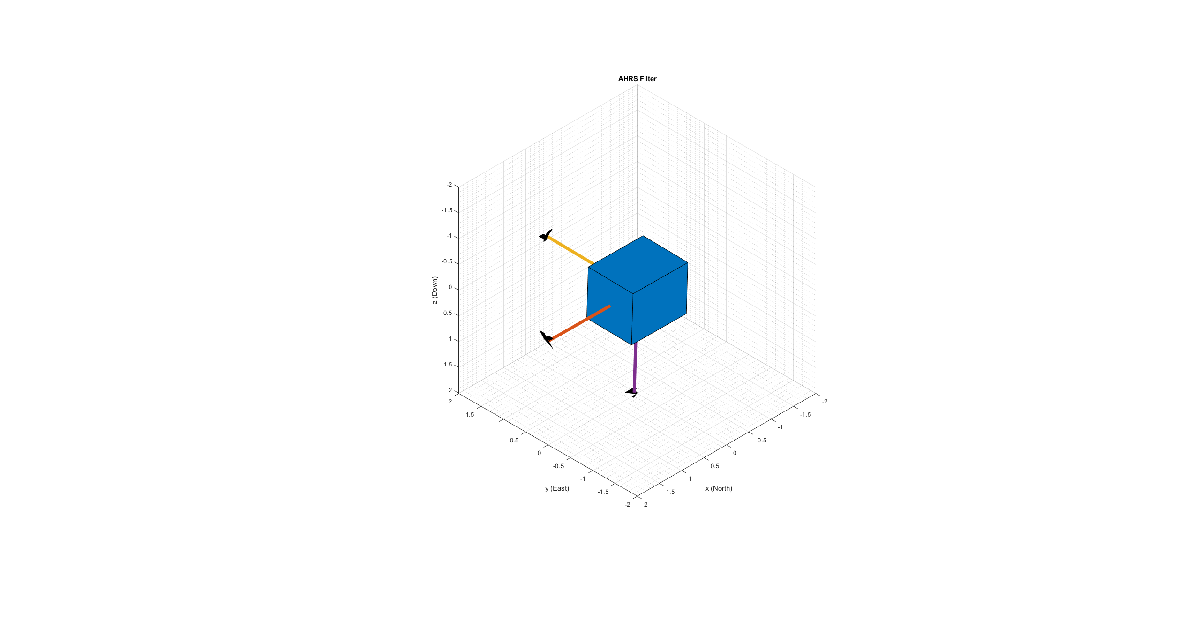
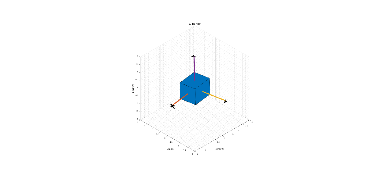
This example shows how to get data from a Bosch BNO055 IMU sensor through an HC-05 Bluetooth® module, and to use the 9-axis AHRS fusion algorithm on the sensor data to compute orientation of the device. The example creates a figure which gets updated as you move the device.
BNO055 is a 9-axis sensor with accelerometer, gyroscope, and magnetometer. Accelerometer measures acceleration, gyroscope measures angular velocity, and magnetometer measures magnetic field in x-, y- and z- axes.
Required MathWorks Products
MATLAB®
MATLAB Support Package for Arduino® Hardware
Instrument Control Toolbox™
Sensor Fusion and Tracking Toolbox™ or Navigation Toolbox™
Required Hardware
Arduino Uno
Bosch BNO055 Sensor
HC-05 Bluetooth® Module
Hardware Connection

Connect the SDA, SCL, GND, and the VCC pins of the BNO055 sensor to the corresponding pins on the Arduino Uno board with the connections:
SDA - A4
SCL - A5
VCC - +3.3V
GND - GND
Connect the TX, RX, GND and VCC pins of the HC-05 module to the corresponding pins on the Arduino Uno board. This example uses the connections:
TX – Digital Pin 0 (RX)
RX – Digital Pin 1 (TX)
VCC – 5V
GND – GND
Ensure that the connections to the sensors and Bluetooth® module are intact. It is recommended to use a BNO055 shield for Arduino Uno (Arduino 9 Axis Motion Shield). See Troubleshooting Sensors to debug the sensor related issues.
Set Up and Configure Arduino for Bluetooth Communication
Configure the Arduino Uno board to communicate through Bluetooth using the arduinosetup command from MATLAB command prompt. See Set Up and Configure Arduino Hardware for steps on how to configure the Arduino board for communication through Bluetooth. Make sure to check the box for I2C Libraries to be included during the Setup.
Create Sensor Object
Create an arduino object.
a = arduino('btspp://98D33230EB9F', 'Uno');
Create the bno055 sensor object in the OperatingMode 'amg'.
 fs = 100; % Sample Rate in Hz
imu = bno055(a,'SampleRate',fs,'OutputFormat','matrix','OperatingMode','amg');
Compensating for Hard Iron and Soft Iron Distortions
Fusion algorithms use magnetometer readings which need to be compensated for magnetic distortions such as hard iron distortion. Hard iron distortions are produced by materials which create a magnetic field, resulting in shifting the origin on the response surface. These distortions can be corrected by subtracting the correction values from the magnetometer readings for each axis. In order to find the correction values,
Rotate the sensor from 0 to 360 degree along each axis.
Use the
magcalfunction to obtain the correction coefficients.
These correction values change with the surroundings.
To obtain correction coefficients for both hard iron and soft iron distortions:
ts = tic;
stopTimer = 50;
magReadings=[];
while(toc(ts) < stopTimer)
    % Rotate the sensor along x axis from 0 to 360 degree.
    % Take 2-3 rotations to improve accuracy.
    % For other axes, rotate along that axes.
   [accel,gyro,mag] = read(imu);
   magReadings = [magReadings;mag];
end

[A, b] = magcal(magReadings); % A = 3x3 matrix for soft iron correction
                              % b = 3x1 vector for hard iron correction
Aligning the Axis of BNO055 Sensor with NED Coordinates
Sensor Fusion algorithms used in this example use North-East-Down (NED) as a fixed, parent coordinate system. In the NED reference frame, the x-axis points north, the y-axis points east, and the z-axis points down. Depending on the algorithm, north may either be the magnetic north or true north. The algorithms in this example use the magnetic north. The algorithms used here expect all the sensors in the object to have their axes aligned with NED convention. The sensor values have to be inverted so that they are in accordance with the NED coordinates.
Tuning Filter Parameters
The algorithms used in this example, when properly tuned, enable estimation of orientation and are robust against environmental noise sources. You must consider the situations in which the sensors are used and tune the filters accordingly. See Custom Tuning of Fusion Filters (Sensor Fusion and Tracking Toolbox) for more details related to tuning filter parameters.
The example uses ahrsfilter to demonstrate orientation estimation. See Determine Orientation Using Inertial Sensors (Sensor Fusion and Tracking Toolbox) for more details related to inertial fusion algorithms.
Accelerometer-Gyroscope-Magnetometer Fusion
An attitude and heading reference system (AHRS) consists of a 9-axis system that uses an accelerometer, gyroscope, and magnetometer to compute the orientation of the device. The ahrsfilter produces a smoothly changing estimate of orientation of the device, while correctly estimating the north direction. The ahrsfilter has the ability to remove gyroscope bias and can also detect and reject mild magnetic jamming.
The following code snippets use ahrsfilter System object™ to determine the orientation of the sensor and create a figure that gets updated as you move the sensor. The initial position of the sensor should be such that the device x-axis is pointing towards magnetic north, the device y-axis is pointing to east and the device z-axis is pointing downwards. You could use a cellphone or compass to determine magnetic north.
% GyroscopeNoise, AccelerometerNoise and MagnetometerNoise are determined from the BNO055 datasheet using the following formula
% NoisePower = OutputNoisePowerDensityrms^2 * Bandwidth

GyroscopeNoiseBNO055 = 3.05e-06; % GyroscopeNoise (variance value) in units of (rad/s)^2
AccelerometerNoiseBNO055 = 67.53e-06; % AccelerometerNoise (variance value)in units of (m/s^2)^2
MagnetometerNoiseBNO055 = 1; %MagnetometerNoise (variance value) in units of uT^2

viewer = HelperOrientationViewer('Title',{'AHRS Filter'});

FUSE = ahrsfilter('SampleRate',imu.SampleRate,'GyroscopeNoise',GyroscopeNoiseBNO055,'AccelerometerNoise',AccelerometerNoiseBNO055,'MagnetometerNoise',MagnetometerNoiseBNO055);

stopTimer=10;
After executing the below code snippet, slowly move the sensor and check if the motion in the figure matches the motion of the sensor. Increase the stopTimer value, if you need to track the orientation for longer time.
magx_correction = b(1);
magy_correction = b(2);
magz_correction = b(3);

ts = tic;
while(toc(ts) < stopTimer)
    [accel,gyro,mag] = read(imu);
    % Align coordinates in accordance with NED convention
    accel = [-accel(:,1), accel(:,2), accel(:,3)];
    gyro = [gyro(:,1), -gyro(:,2), -gyro(:,3)];
    mag = [(mag(:,1)-magx_correction), -(mag(:,2)- magy_correction), -(mag(:,3)-magz_correction)] * A;
    rotators = FUSE(accel,gyro,mag);
    for j = numel(rotators)
      viewer(rotators(j));
    end
end
If the sensor is stationary at the initial position where the device x-axis points to the magnetic north, the device y-axis points to the east, and the device z-axis points downwards, the x-axis in the figure will be parallel to and aligned with the positive x-axis, the y-axis in the figure will be parallel to and aligned with the positive y-axis, and the z-axis in the figure will be parallel to and aligned with the positive z-axis.


Clean Up
When the connection is no longer needed, release and clear the objects.
release(imu);
delete(imu);
clear;
Things to Try
You can try this example with other sensors such as InvenSense MPU-6050, MPU-9250, and STMicroelectronics LSM9DS1.