主要内容

nullweights

Nulling weights

Since R2026a

    Description

    W = nullweights(pos,angd,angn) returns the beamforming weights, W, of the sensor array defined in pos, for the desired direction specified in angd while generating nulls in the directions specified in angn. W is an N-element column vector containing the beamforming weights. N is the number of elements in the sensor array and elements are assumed to be isotropic.

    example

    Examples

    collapse all

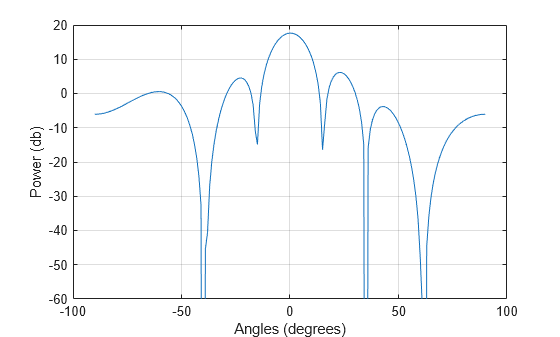
    Beamform an 8-element ULA towards boresight and null out interference from-40, 35, and 62 azimuth angle.

    Create eight isotropic sensors on a ULA one-half wavelength apart.

    N = 8;
    antposn = (0:N-1)*0.5;

    Set the signal arrival angle and interference arrival angles.

    angd = 0;
    angn = [-40 35 62];

    Solve for the nulling weights.

    nullwts = nullweights(antposn,angd,angn);

    Find and plot the array factor in the span -90 to 90.

    angplot = -90:90;
    af = arrayfactor(antposn,angplot,nullwts);

    Plot the array factor.

    plot(angplot,mag2db(abs(af)))
    xlabel("Angles (degrees)")
    ylabel("Power (db)")
    ylim([-60 20])
    grid on

    Figure contains an axes object. The axes object with xlabel Angles (degrees), ylabel Power (db) contains an object of type line.

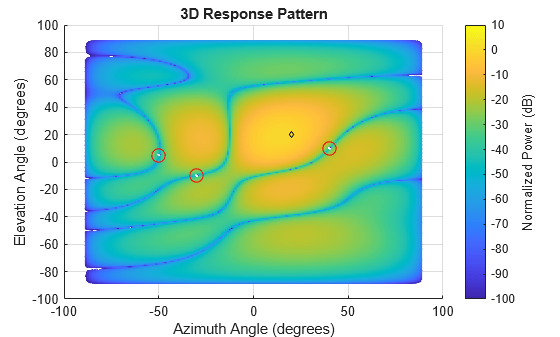
    Using a square 4-by-4 URA array, steer three nulls scanning both in the azimuth and elevation directions. The array operates at 300 MHz.

    First, create a 4-by-4 URA with cosine antenna elements spaced at half-wavelength.

    ant = phased.URA(4,0.5, ...
        Element = phased.CosineAntennaElement);

    Steer the array to 20 azimuth and 20 elevation. Place the nulls at

    Azimuth

    Elevation

    40

    10

    -30

    -10

    -50

    5

    angd = [20;20];
    angn = [40 -30 -50;10 -10 5];
    c = physconst("LightSpeed");
    fc = 300e6;
    lambda = c/fc;

    Compute the nulling weights.

    wn = nullweights( ...
        getElementPosition(ant)/lambda,angd,angn);

    Display the array beam power pattern with the location of the MRA and the nulls.

    pattern(ant,fc,Type = "powerdb", ...
        CoordinateSystem = "rectangular", ...
        Weights = wn)
    view(0,90)
    hold on
    plot(angd(1),angd(2),"kd", ...
        MarkerSize = 3)
    plot(angn(1,:),angn(2,:),"ro", ...
        MarkerSize = 10)
    hold off

    Figure contains an axes object. The axes object with title 3D Response Pattern, xlabel Azimuth Angle (degrees), ylabel Elevation Angle (degrees) contains 3 objects of type surface, line. One or more of the lines displays its values using only markers

    Input Arguments

    collapse all

    Sensor array element positions, specified as a 1-by-N real-valued vector, a 2-by-N real-valued matrix, or a 3-by-N real-valued matrix. N is the number of array elements.

    • If pos is a 1-by-N vector, then it represents the y-coordinates of elements of a linear array along y-axis.

    • If pos is a 2-by-N matrix, then it represents a planar array lying in the yz-plane. In this case, each column represents the [y;z]-coordinates of the corresponding element.

    • If pos is a 3-by-N matrix, then the array has an arbitrary shape. In this case, each column of pos represents the [x;y;z] coordinates of the array.

    Units are specified in terms of signal wavelength.

    Data Types: double

    Desired direction, specified as a scalar or two-element real-valued vector.

    • When angd is a scalar, it contains the azimuth angle of the desired direction. The corresponding elevation angle is assumed to be zero.

    • When angd Is a 2-element vector, it specifies the desired direction in space in the form [azimuth; elevation]. The azimuth angle must be between –180° and 180° degrees and the elevation angle must be between –90° and 90°. The azimuth angle is defined in the xy-plane and is the angle measured from the x-axis, which is also the array normal direction, toward the y-axis. The elevation angle is defined as the angle from the xy-plane toward the z axis.

    Angle units are in degrees.

    Example: [40 10]

    Data Types: double

    Nulling directions, specified as a real-valued length M vector or real-valued 2-by-M matrix where M is the number of nulling directions.

    • When angn is a real-valued length M vector, it contains the azimuth angles of the nulling directions. The corresponding elevation angles are assumed to be zero.

    • When angn is a real-valued 2-by-M matrix, it specifies the nulling directions in the form [azimuth;elevation]. The azimuth angles must lie between –180° and 180° degrees and the elevation angles must lie between –90° and 90°. The azimuth angles are defined in the xy-plane and are measured from the x-axis, which is also the array normal direction, toward the z-axis. The elevation angles are defined as the angles from the xy-plane toward the z axis.

    Angle units are in degrees.

    Example: [40 10]

    Data Types: double

    Output Arguments

    collapse all

    Nulling weights, returned as a complex-valued length-N column vector. N is the number of array elements.

    Data Types: double
    Complex Number Support: Yes

    References

    [1] Harry Van Trees, Optimum Array Processing, 2002

    [2] Sidney Applebaum, Adaptive Arrays, IEEE Transactions on Antennas and Propagation, Vol. AP-24, No. 5, September 1976.

    Version History

    Introduced in R2026a