step
System object: phased.SumDifferenceMonopulseTracker2D
Namespace: phased
Perform monopulse tracking using URA
Syntax
ESTANG = step(H,X,STANG)
Description
Note
Starting in R2016b, instead of using the step method
to perform the operation defined by the System object™, you can
call the object with arguments, as if it were a function. For example, y
= step(obj,x) and y = obj(x) perform
equivalent operations.
ESTANG = step(H,X,STANG)ESTANG of the input signal, X,
based on an initial guess of the direction.
Note
The object performs an initialization the first time the object is executed. This
initialization locks nontunable properties
and input specifications, such as dimensions, complexity, and data type of the input data.
If you change a nontunable property or an input specification, the System object issues an error. To change nontunable properties or inputs, you must first
call the release method to unlock the object.
Input Arguments
| Tracker object of type |
| Input signal, specified as a row vector whose number of columns corresponds to number of channels. You can specify this argument as single or double precision. The size of the first dimension of the input matrix can vary to simulate a changing signal length. A size change can occur, for example, in the case of a pulse waveform with variable pulse repetition frequency. |
| Initial guess of the direction, specified as a 2-by-1 vector in the form
|
Output Arguments
| Estimate of incoming direction, returned as a 2-by-1 vector
in the form |
Examples
Algorithms
The sum-and-difference monopulse algorithm is used to the estimate the arrival direction of a narrowband signal impinging upon a uniform linear array (ULA). First, compute the conventional response of an array steered to an arrival direction φ0. For a ULA, the arrival direction is specified by the broadside angle. To specify that the maximum response axis (MRA) point towards the φ0 direction, set the weights to be
where d is the element spacing and k = 2π/λ is the wavenumber. An incoming plane wave, coming from any arbitrary direction φ, is represented by
The conventional response of this array to any incoming plane wave is given by and is shown in the polar plot below as the Sum Pattern. The array is designed to steer towards φ0 = 30°.
The second pattern, called the Difference Pattern, is obtained by using phased-reversed weights. The weights are determined by phase-reversing the latter half of the conventional steering vector. For an array with an even number of elements, the phase-reversed weights are
(For an array with an odd number of elements, the middle weight is set to zero). The multiplicative factor –i is used for convenience. The response of the difference array to the incoming vector is
This figure shows the sum and difference beam patterns of a four-element uniform linear array (ULA) steered 30° from broadside. The array elements are spaced at one-half wavelength. The sum pattern shows that the array has its maximum response at 30° and the difference pattern has a null at 30°.
![]()
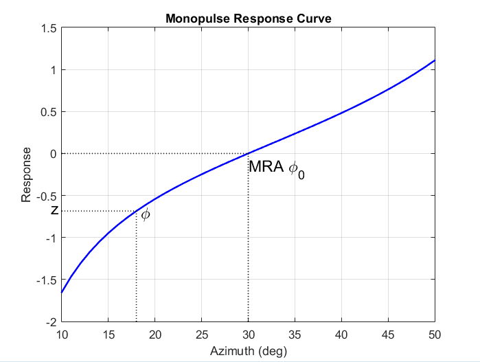
The monopulse response curve is obtained by dividing the difference pattern by the sum pattern and taking the real part.
To use the monopulse response curve to obtain the arrival angle, φ, of a narrowband signal, x, compute
and invert the response curve, φ = R-1(z), to obtain φ.
The response curve is not generally single valued and can only be inverted when arrival angles lie within the main lobe where it is single valued This figure shows the monopulse response curve within the main lobe of the four-element ULA array.

There are two desirable properties of the monopulse response curve. The first is that it have a steep slope. A steep slope ensures robustness against noise. The second property is that the mainlobe be as wide as possible. A steep slope is ensure by a larger array but leads to a smaller mainlobe. You will need to trade off one property with the other.
For further details, see [1].
References
[1] Seliktar, Y. Space-Time Adaptive Monopulse Processing. Ph.D. Thesis. Georgia Institute of Technology, Atlanta, 1998.
[2] Rhodes, D. Introduction to Monopulse. Dedham, MA: Artech House, 1980.