uv2phithetapat
Convert radiation pattern from u/v form to phi/theta form
Syntax
Description
pat_phitheta = uv2phithetapat(pat_uv,u,v)pat_phitheta in φ/θ
angle coordinates instead of u/v space coordinates. pat_uv samples
the pattern at u angles in u and v angles
in v. The pat_phitheta matrix
uses a default grid that covers φ values from 0 to 360 degrees
and θ values from 0 to 90 degrees. In this grid, pat_phitheta is
uniformly sampled with a step size of 1 for φ and θ. The
function interpolates to estimate the response of the antenna at a
given direction.
[
returns vectors containing the φ and θ angles at which
pat_phitheta,phi_pat,theta_pat]
= uv2phithetapat(___)pat_phitheta samples the pattern, using any of the input
arguments in the previous syntaxes.
Examples
Convert a radiation pattern to φ-θ space with the angles spaced 1° apart.
Define the pattern in terms of u and v. Because u and v values outside the unit circle are not physical, set the pattern values in this region to zero.
u = -1:0.01:1;
v = -1:0.01:1;
[u_grid,v_grid] = meshgrid(u,v);
pat_uv = sqrt(1 - u_grid.^2 - v_grid.^2);
pat_uv(hypot(u_grid,v_grid) >= 1) = 0;
Convert the pattern to φ-θ space.
[pat_phitheta,phi,theta] = uv2phithetapat(pat_uv,u,v);
Convert a radiation pattern to space with the angles spaced one degree apart.
Define the pattern in terms of and . For values outside the unit circle, and are undefined, and the pattern value is 0.
u = -1:0.01:1;
v = -1:0.01:1;
[u_grid,v_grid] = meshgrid(u,v);
pat_uv = sqrt(1 - u_grid.^2 - v_grid.^2);
pat_uv(hypot(u_grid,v_grid) >= 1) = 0;
Convert the pattern to space. Store the and angles for use in plotting.
[pat_phitheta,phi,theta] = uv2phithetapat(pat_uv,u,v);
Plot the result.
H = surf(phi,theta,pat_phitheta);
H.LineStyle = 'none';
xlabel('Phi (degrees)');
ylabel('Theta (degrees)');
zlabel('Pattern');
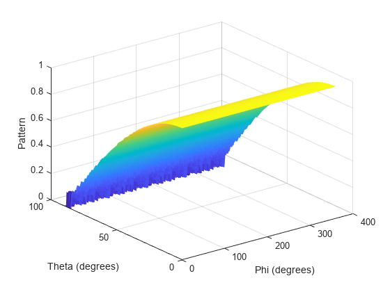
Convert a radiation pattern to space with the angles spaced five degrees apart.
Define the pattern in terms of and . For values outside the unit circle, and are undefined, and the pattern value is 0.
u = -1:0.01:1;
v = -1:0.01:1;
[u_grid,v_grid] = meshgrid(u,v);
pat_uv = sqrt(1 - u_grid.^2 - v_grid.^2);
pat_uv(hypot(u_grid,v_grid) >= 1) = 0;
Define the set of and angles at which to sample the pattern. Then, convert the pattern.
phi = 0:5:360;
theta = 0:5:90;
pat_phitheta = uv2phithetapat(pat_uv,u,v,phi,theta);
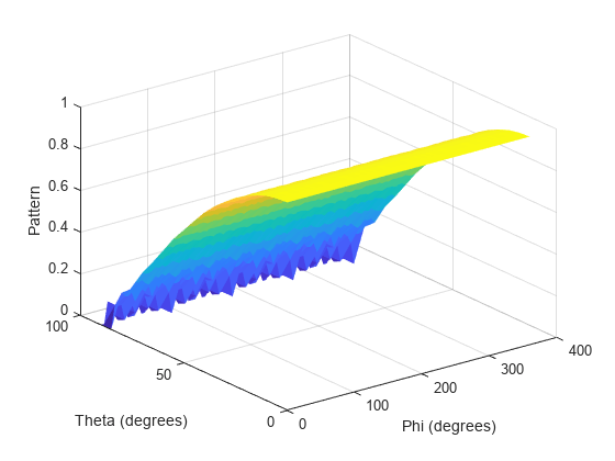
Plot the result.
H = surf(phi,theta,pat_phitheta);
H.LineStyle = 'none';
xlabel('Phi (degrees)');
ylabel('Theta (degrees)');
zlabel('Pattern');
Input Arguments
Output Arguments
More About
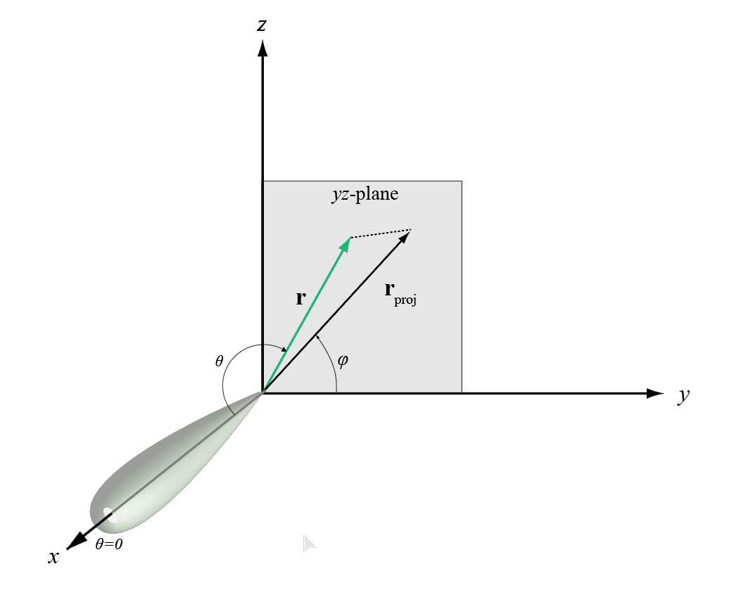
The phi angle (φ) is the angle from the positive y-axis to the vector’s orthogonal projection onto the yz plane. The angle is positive toward the positive z-axis. The phi angle is between 0 and 360 degrees. The theta angle (θ) is the angle from the x-axis to the vector itself. The angle is positive toward the yz plane. The theta angle is between 0 and 180 degrees.
The figure illustrates phi and theta for a vector that appears as a green solid line.
The coordinate transformations between φ/θ and az/el are described by the following equations
Extended Capabilities
Version History
Introduced in R2012a