phased.CustomAntennaElement
Custom antenna element
Description
The phased.CustomAntennaElement
System object™ models an antenna element with a custom spatial response pattern. The response
pattern can be defined for polarized or non-polarized fields.
To create a custom antenna element:
Create the
phased.CustomAntennaElementobject and set its properties.Call the object with arguments, as if it were a function.
To learn more about how System objects work, see What Are System Objects?
Creation
Description
antenna = phased.CustomAntennaElementantenna, with default property values. The default
response pattern is spatially isotropic.
antenna = phased.CustomAntennaElement(Name,Value)antenna, with each specified
property Name set to the specified Value. You can specify additional name-value pair
arguments in any order as
(Name1,Value1,...,NameN,ValueN).
For example, the output response of the object depends on whether polarization is set or not.
To create a nonpolarized response pattern, set the
SpecifyPolarizationPatternproperty tofalse(default). Then, use theMagnitudePatternandPhasePatternproperties to define the response pattern.To create a polarized response pattern, set the
SpecifyPolarizationPatternproperty totrue. Then, use any or all of theHorizontalMagnitudePattern,HorizontalPhasePattern,VerticalMagnitudePattern, andVerticalPhasePatternproperties to define the response pattern.
Properties
Unless otherwise indicated, properties are nontunable, which means you cannot change their
values after calling the object. Objects lock when you call them, and the
release function unlocks them.
If a property is tunable, you can change its value at any time.
For more information on changing property values, see System Design in MATLAB Using System Objects.
Frequencies at which the frequency response and antenna patterns are to be returned, specified as a 1-by-L row vector. The elements of the vector must be in increasing order. The antenna element has no response outside the frequency range specified by the minimum and maximum elements of the frequency vector. Units are in Hz.
Example: [200:50:300]*1e6
Data Types: double
Frequency responses at the frequencies defined in
FrequencyVector property, specified as a
1-by-L row vector. L equals the length of the
vector specified in the FrequencyVector property. Units are in
dB.
Example: [0 6 0]
Data Types: double
Coordinate system of custom antenna pattern, specified 'az-el' or
'phi-theta'. When you specify 'az-el', use the
AzimuthAngles and ElevationAngles properties
to specify the pattern coordinates system. When you specify
'phi-theta', use the PhiAngles and
ThetaAngles properties to specify the pattern coordinates
system.
Data Types: char
Specify the azimuth angles as a length-P vector. These angles are the azimuth angles where the custom radiation pattern is specified. P must be greater than 2. The azimuth angles must lie between –180° and 180° and be in strictly increasing order. Units are in degrees.
Example: [30 40 50]
Dependencies
To enable this property, set the PatternCoordinateSystem
property to 'az-el'.
Data Types: double
Specify the elevation angles as a length-Q vector. These angles are the elevation angles where the custom radiation pattern is specified. Q must be greater than 2. The elevation angles must lie between –90° and 90° and be in strictly increasing order. Units are in degrees.
Example: [-30 0 +30]
Dependencies
To enable this property, set the PatternCoordinateSystem
property to 'az-el'.
Data Types: double
Phi angles used to represent the element response pattern in phi-theta coordinates, specified as a real-valued P-length vector. Phi angles lie between 0° and 360°. P must be greater than 2. Look here for definitions of Phi and Theta Angles.
Example: [90:180]
Dependencies
To enable this property, set the PatternCoordinateSystem
property to 'phi-theta'.
Data Types: double
Theta angles used to represent the element response pattern in phi-theta coordinates, specified as a real-valued Q-length vector. The theta angle lies between 0° and 180°. Look here for definitions of Phi and Theta Angles. Q must be greater than 2.
Example: [40:80]
Dependencies
To enable this property, set the PatternCoordinateSystem
property to 'phi-theta'.
Data Types: double
Polarized array response, specified as false or
true.
When the
SpecifyPolarizationPatternproperty is set tofalse, the antenna element transmits or receives non-polarized radiation. In this case, use theMagnitudePatternproperty to set the antenna response pattern.When the
SpecifyPolarizationPatternproperty is set totrue, the antenna element transmits or receives polarized radiation. In this case, use theHorizontalMagnitudePatternandHorizontalPhasePatternproperties to set the horizontal polarization response pattern and theVerticalMagnitudePatternandVerticalPhasePatternproperties to set the vertical polarization response pattern.
Data Types: logical
The magnitude of the combined polarization antenna radiation, pattern specified as a
Q-by-P matrix or a
Q-by-P-by-L array. This
property is used only when the SpecifyPolarizationPattern property
is set to false. Magnitude units are in dB.
If the value of this property is a Q-by-P matrix, the same pattern is applied to all frequencies specified in the
FrequencyVectorproperty.If the value is a Q-by-P-by-L array, each Q-by-P page of the array specifies a pattern for the corresponding frequency specified in the
FrequencyVectorproperty.
If the pattern contains a NaN at any azimuth and elevation
direction, it is converted to -Inf, indicating zero response in that
direction. The custom antenna object uses interpolation to estimate the response of the
antenna at a given direction. To avoid interpolation errors, the custom response pattern
must contain azimuth angles in the range [–180,180] degrees. Set the
range of elevation angles to [–90,90] degrees.
Data Types: double
The phase of the combined polarization antenna radiation pattern, specified as a
Q-by-P matrix or a
Q-by-P-by-L array. This
property is used only when the SpecifyPolarizationPattern property
is set to false. Units are in degrees.
If the value of this property is a Q-by-P matrix, the same pattern is applied to all frequencies specified in the
FrequencyVectorproperty.If the value is a Q-by-P-by-L array, each Q-by-P page of the array specifies a pattern for the corresponding frequency specified in the
FrequencyVectorproperty.
The custom antenna object uses interpolation to estimate the response of the antenna at a given direction. To avoid interpolation errors, the custom response pattern must contain azimuth angles in the range [–180°,180°]. Set the range of elevation angles to [–90°,90°].
Data Types: double
The magnitude of the horizontal polarization component of the antenna radiation pattern, specified as a real-valued Q-by-P matrix or real-valued a Q-by-P-by-L array. Magnitude units are in dB.
If the value of this property is a Q-by-P matrix, the same pattern is applied to all frequencies specified in the
FrequencyVectorproperty.If the value is a Q-by-P-by-L array, each Q-by-P page of the array specifies a pattern for the corresponding frequency specified in the
FrequencyVectorproperty.
If the magnitude pattern contains a NaN at any azimuth and
elevation direction, it is converted to -Inf, indicating zero
response in that direction. The custom antenna object uses interpolation to estimate the
response of the antenna at a given direction. To avoid interpolation errors, the custom
response pattern must contain azimuth angles in the range
[–180,180]° and elevation angles in the range
[–90,90]°.
Dependencies
To enable this property, set the SpecifyPolarizationPattern
property to true.
Data Types: double
The phase of the horizontal polarization component of the antenna radiation pattern,
specified as a real-valued Q-by-P matrix or a
real-valued Q-by-P-by-L array.
This property is used only when the SpecifyPolarizationPattern
property is set to true. Phase units are in degrees.
If the value of this property is a Q-by-P matrix, the same pattern is applied to all frequencies specified in the
FrequencyVectorproperty.If the value is a Q-by-P-by-L array, each Q-by-P page of the array specifies a pattern for the corresponding frequency specified in the
FrequencyVectorproperty.
The custom antenna object uses interpolation to estimate the response of the antenna
at a given direction. To avoid interpolation errors, the custom response pattern must
contain azimuth angles in the range [–180,180]° and elevation
angles in the range [–90,90]°.
Dependencies
To enable this property, set the SpecifyPolarizationPattern
property to true.
Data Types: double
The magnitude of the vertical polarization component of the antenna radiation
pattern specified as a Q-by-P matrix or a
Q-by-P-by-L array. This
property is used only when the SpecifyPolarizationPattern property
is set to true. Magnitude units are in dB.
If the value of this property is a Q-by-P matrix, the same pattern is applied to all frequencies specified in the
FrequencyVectorproperty.If the value is a Q-by-P-by-L array, each Q-by-P page of the array specifies a pattern for the corresponding frequency specified in the
FrequencyVectorproperty.
If the pattern contains a NaN at any azimuth and elevation
direction, it is converted to -Inf, indicating zero response in that
direction. The custom antenna object uses interpolation to estimate the response of the
antenna at a given direction. To avoid interpolation errors, the custom response pattern
must contain azimuth angles in the range[–180,180]° and
elevation angles in the range [–90,90]°.
Dependencies
To enable this property, set the SpecifyPolarizationPattern
property to true.
Data Types: double
The phase of the vertical polarization component of the antenna radiation pattern,
specified as a Q-by-P matrix or a
Q-by-P-by-L array. This
property is used only when the SpecifyPolarizationPattern property
is set to true. Phase units are in degrees.
If the value of this property is a Q-by-P matrix, the same pattern is applied to all frequencies specified in the
FrequencyVectorproperty.If the value is a Q-by-P-by-L array, each Q-by-P page of the array specifies a pattern for the corresponding frequency specified in the
FrequencyVectorproperty.
The custom antenna object uses interpolation to estimate the response of the antenna
at a given direction. To avoid interpolation errors, the custom response pattern must
contain azimuth angles in the range [–180,180]° and elevation
angles in the range [–90,90]°.
Dependencies
To enable this property, set the SpecifyPolarizationPattern
property to true.
Data Types: double
Set this property to true to align the antenna element to an
array normal. The antenna pattern is rotated so that the x-axis of
the element coordinate system points along the array normal. This property is used only
when the antenna element belongs to an array. Use the property in conjunction with the
ArrayNormal property of the phased.URA and phased.UCA System objects. Set this
property to false to use the element pattern without rotation.
Data Types: logical
Usage
Syntax
Description
RESP = antenna(FREQ,ANG)RESP at operating frequencies
specified in FREQ and directions specified in
ANG. The form of RESP depends upon whether the
antenna element supports polarization as determined by the
SpecifyPolarizationPattern property. If
SpecifyPolarizationPattern is set to false,
RESP is an M-by-L matrix
containing the antenna response at the M angles specified in
ANG and at the L frequencies specified in
FREQ. If SpecifyPolarizationPattern is set to
true, RESP is a MATLAB®
struct containing two fields, RESP.H and
RESP.V, representing the antenna's response in horizontal and
vertical polarization, respectively. Each field is an
M-by-L matrix containing the antenna response at
the M angles specified in ANG and at the
L frequencies specified in FREQ.
Note
The object performs an initialization the first time the object is executed. This
initialization locks nontunable properties
and input specifications, such as dimensions, complexity, and data type of the input data.
If you change a nontunable property or an input specification, the System object issues an error. To change nontunable properties or inputs, you must first
call the release method to unlock the object.
Input Arguments
Operating frequency of the antenna element, specified as a nonnegative scalar or nonnegative, real-valued 1-by-L row vector. Frequency units are in Hz.
FREQ must lie within the range of values specified by the
FrequencyRange or the FrequencyVector
property of the element. Otherwise, the element produces no response and the response is
returned as –Inf. Element objects use the
FrequencyRange property, except for phased.CustomAntennaElement, which uses the
FrequencyVector property.
Example: [1e8 2e6]
Data Types: double
Azimuth and elevation angles of the response directions, specified as a real-valued 1-by-M row vector or a real-valued 2-by-M matrix, where M is the number of angular directions. Angle units are in degrees. The azimuth angle must lie in the range –180° to 180°, inclusive. The elevation angle must lie in the range –90° to 90°, inclusive.
If
ANGis a 1-by-M vector, each element specifies the azimuth angle of the direction. In this case, the corresponding elevation angle is assumed to be zero.If
ANGis a 2-by-M matrix, each column of the matrix specifies the direction in the form[azimuth;elevation].
The azimuth angle is the angle between the x-axis and the projection of the direction vector onto the xy-plane. This angle is positive when measured from the x-axis toward the y-axis. The elevation angle is the angle between the direction vector and xy-plane. This angle is positive when measured toward the z-axis. See the definition of Azimuth and Elevation Angles.
Example: [110 125; 15 10]
Data Types: double
Output Arguments
Voltage response of antenna element, returned as a complex-valued
M-by-L matrix. In this matrix,
M represents the number of angles specified in
ANG and L represents the number of
frequencies specified in FREQ.
Data Types: double
Object Functions
To use an object function, specify the
System object as the first input argument. For
example, to release system resources of a System object named obj, use
this syntax:
release(obj)
beamwidth | Compute and display beamwidth of sensor element pattern |
directivity | Directivity of antenna or transducer element |
isPolarizationCapable | Antenna element polarization capability |
pattern | Plot antenna or transducer element directivity and patterns |
patternAzimuth | Plot antenna or transducer element directivity and pattern versus azimuth |
patternElevation | Plot antenna or transducer element directivity and pattern versus elevation |
Examples
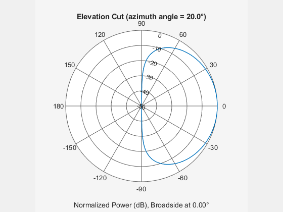
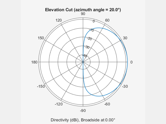
Create a user-defined antenna with a cosine pattern. Then, plot an elevation cut of the antenna's power response.
The user-defined pattern is omnidirectional in the azimuth direction and has a cosine pattern in the elevation direction. Assume the antenna operates at 1 GHz. Obtain the response at 20° azimuth and 30° elevation.
fc = 1e9;
azang = -180:180;
elang = -90:90;
magpattern = mag2db(repmat(cosd(elang)',1,numel(azang)));
phasepattern = zeros(size(magpattern));
antenna = phased.CustomAntennaElement('AzimuthAngles',azang, ...
    'ElevationAngles',elang,'MagnitudePattern',magpattern, ...
    'PhasePattern',phasepattern);
resp = antenna(fc,[20;30])
resp =
0.8660
Plot an elevation cut of the power response.
pattern(antenna,fc,20,-90:90,'CoordinateSystem','polar','Type','powerdb')
Plot an elevation cut of the directivity.
pattern(antenna,fc,20,-90:90,'CoordinateSystem','polar','Type','directivity')
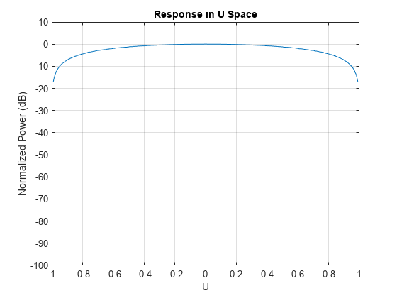
Define a custom antenna in u-v space. Then, calculate and plot the response.
Define the radiation pattern (in dB) of an antenna in terms of u and v coordinates within the unit circle.
u = -1:0.01:1;
v = -1:0.01:1;
[u_grid,v_grid] = meshgrid(u,v);
pat_uv = sqrt(1 - u_grid.^2 - v_grid.^2);
pat_uv(hypot(u_grid,v_grid) >= 1) = 0;
Create an antenna with this radiation pattern. Convert u-v coordinates to azimuth and elevation coordinates.
[pat_azel,az,el] = uv2azelpat(pat_uv,u,v);
array = phased.CustomAntennaElement('AzimuthAngles',az,'ElevationAngles',el, ...
    'MagnitudePattern',mag2db(pat_azel),'PhasePattern',45*ones(size(pat_azel)));
Calculate the response in the direction u = 0.5, v = 0. Assume the antenna operates at 1 GHz. The output of the step method is in linear units.
dir_uv = [0.5;0];
dir_azel = uv2azel(dir_uv);
fc = 1e9;
resp = array(fc,dir_azel)
resp =
0.6124 + 0.6124i
Plot the 3D response in u-v coordinates.
pattern(array,fc,[-1:.01:1],[-1:.01:1],'CoordinateSystem','uv','Type','powerdb')

Display the antenna response as a line plot in u-v coordinates.
pattern(array,fc,[-1:.01:1],0,'CoordinateSystem','uv','Type','powerdb')
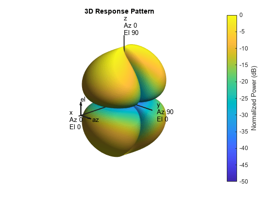
Model a short dipole antenna oriented along the -axis of the local antenna coordinate system. For this type of antenna, the horizontal and vertical components of the electric field are given by and .
Specify a normalized radiation pattern of a short dipole antenna terms of azimuth, , and elevation, , coordinates. The vertical and horizontal radiation patterns are normalized to a maximum of unity.
az = [-180:180];
el = [-90:90];
[az_grid,el_grid] = meshgrid(az,el);
horz_pat_azel = ...
    mag2db(abs(sind(az_grid)));
vert_pat_azel = ...
    mag2db(abs(sind(el_grid).*cosd(az_grid)));
Set up the antenna. Specify the SpecifyPolarizationPattern property to produce polarized radiation. In addition, use the HorizontalMagnitudePattern and VerticalMagnitudePattern properties to specify the pattern magnitude values. The HorizontalPhasePattern and VerticalPhasePattern properties take default values of zero.
antenna = phased.CustomAntennaElement(...
    'AzimuthAngles',az,'ElevationAngles',el,...
    'SpecifyPolarizationPattern',true,...
    'HorizontalMagnitudePattern',horz_pat_azel,...
    'VerticalMagnitudePattern',vert_pat_azel);
Assume the antenna operates at 1 GHz.
fc = 1e9;
Display the vertical response pattern.
pattern(antenna,fc,[-180:180],[-90:90],...
    'CoordinateSystem','polar',...
    'Type','powerdb',...
    'Polarization','V')
Display the horizontal response pattern.
pattern(antenna,fc,[-180:180],[-90:90],...
    'CoordinateSystem','polar',...
    'Type','powerdb',...
    'Polarization','H')
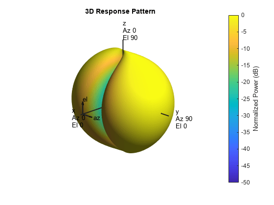
The combined polarization response, shown below, illustrates the -axis null of the dipole.
pattern(antenna,fc,[-180:180],[-90:90],...
    'CoordinateSystem','polar',...
    'Type','powerdb',...
    'Polarization','combined')
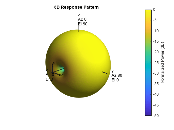
Define a custom antenna in u-v space. Show how the array response pattern is affected by the choice of the MatchArrayNormal property of the phased.CustomAntennaElement.
Define the response pattern (in dB) of an antenna as a function of u and v coordinates within the unit circle. The antenna operates at 1 GHz.
fc = 1e9;
c = physconst('LightSpeed');
u = -1:0.01:1;
v = -1:0.01:1;
[u_grid,v_grid] = meshgrid(u,v);
pat_uv = sqrt(1 - u_grid.^2 - v_grid.^2);
pat_uv(hypot(u_grid,v_grid) >= 1) = 0;
Create a custom antenna with this pattern. Convert u-v coordinates to azimuth and elevation coordinates. Set MatchArrayNormal to false.
[pat_azel,az,el] = uv2azelpat(pat_uv,u,v);
antenna = phased.CustomAntennaElement('AzimuthAngles',az,'ElevationAngles',el, ...
    'MagnitudePattern',mag2db(pat_azel),'PhasePattern',45*ones(size(pat_azel)), ...
    "MatchArrayNormal",false);
Construct a 3-by-3 URA with this element and display the antenna pattern in 3-D polar coordinates. The element spacing is one-half wavelength. The array normal points along the y-axis.
lam = c/fc;
array = phased.URA('Element',antenna,'Size',[3 3],'ElementSpacing', ...
    [lam/2 lam/2],'ArrayNormal','y');
pattern(array,fc,-180:180,-90:90,'PropagationSpeed',c, ...
    'CoordinateSystem','polar','Type','powerdb','Normalize',true)

The pattern shows the interplay between the element pattern pointing along the x-axis and the array pattern pointing along the y-axis.
Create another custom antenna with the same radiation pattern. Set MatchArrayNormal to true. Then create another array with this element.
antenna2 = phased.CustomAntennaElement('AzimuthAngles',az,'ElevationAngles',el, ...
    'MagnitudePattern',mag2db(pat_azel),'PhasePattern',45*ones(size(pat_azel)), ...
    "MatchArrayNormal",true);
array2 = phased.URA('Element',antenna2,'Size',[3 3],'ElementSpacing', ...
    [lam/2 lam/2],'ArrayNormal','y');
pattern(array2,fc,-180:180,-90:90,'PropagationSpeed',c, ...
    'CoordinateSystem','polar','Type','powerdb','Normalize',true)
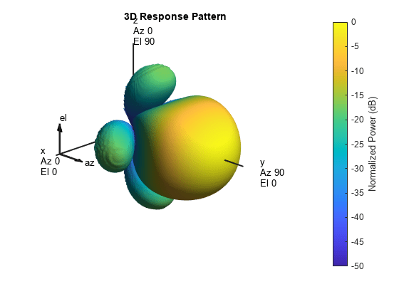
This pattern shows the aligned element and array patterns pointing along the y-axis.
Construct a user-defined antenna with an omnidirectional response in azimuth and a cosine pattern in elevation. The antenna operates at 1 GHz. Plot the response pattern. Then, find the antenna response at 30°.
antenna = phased.CustomAntennaElement;
antenna.AzimuthAngles = -180:180;
antenna.ElevationAngles = -90:90;
antenna.MagnitudePattern = mag2db(repmat(cosd(antenna.ElevationAngles)',...
    1,numel(antenna.AzimuthAngles)));
Find the response at 30° elevation for an operating frequency of 1 GHz.
fc = 1.0e9;
resp = antenna(fc,[0;30])
resp =
0.8660
Create a custom antenna element object. The radiation pattern has a cosine dependence on elevation angle but is independent of azimuth angle.
az = -180:90:180;
el = -90:45:90;
elresp = cosd(el);
magpattern = mag2db(repmat(elresp',1,numel(az)));
phasepattern = zeros(size(magpattern));
antenna = phased.CustomAntennaElement('AzimuthAngles',az,...
    'ElevationAngles',el,'MagnitudePattern',magpattern, ...
    'PhasePattern',phasepattern);
Display the radiation pattern.
disp(antenna.MagnitudePattern)
      -Inf      -Inf      -Inf      -Inf      -Inf
   -3.0103   -3.0103   -3.0103   -3.0103   -3.0103
         0         0         0         0         0
   -3.0103   -3.0103   -3.0103   -3.0103   -3.0103
      -Inf      -Inf      -Inf      -Inf      -Inf
Calculate the antenna response at the azimuth-elevation pairs (-30,0) and (-45,0) at 500 MHz.
ang = [-30 0; -45 0];
resp = antenna(500.0e6,ang);
disp(resp)
    0.7071
    1.0000
The following code illustrates how nearest-neighbor interpolation is used to find the antenna voltage response in the two directions. The total response is the product of the angular response and the frequency response.
g = interp2(deg2rad(antenna.AzimuthAngles),...
    deg2rad(antenna.ElevationAngles),...
    db2mag(antenna.MagnitudePattern),...
    deg2rad(ang(1,:))', deg2rad(ang(2,:))','nearest',0);
h = interp1(antenna.FrequencyVector,...
    db2mag(antenna.FrequencyResponse),500e6,'nearest',0);
antresp = h.*g;
Compare the value of antresp to the response of the antenna.
disp(mag2db(antresp))
   -3.0103
         0
Compute the directivity of a custom antenna element.
Define an antenna pattern for a custom antenna element in azimuth-elevation space. The pattern is omnidirectional in the azimuth direction and has a cosine pattern in the elevation direction. Assume the antenna operates at 1 GHz. Get the response at zero degrees azimuth and from -30 to 30 degrees elevation.
fc = 1e9;
azang = [-180:180];
elang = [-90:90];
magpattern = mag2db(repmat(cosd(elang)',1,numel(azang)));
phasepattern = zeros(size(magpattern));
antenna = phased.CustomAntennaElement('AzimuthAngles',azang, ...
    'ElevationAngles',elang,'MagnitudePattern',magpattern, ...
    'PhasePattern',phasepattern);
Calculate the directivities as a function of elevation for 0° azimuth angle.
angs = [0,0,0,0,0,0,0;-30,-20,-10,0,10,20,30];
freq = 1e9;
d = directivity(antenna,freq,angs)
d = 7×1

    0.5115
    1.2206
    1.6279
    1.7609
    1.6279
    1.2206
    0.5115
The directivity is maximum at elevation.
Show that the CustomAntennaElement antenna element supports polarization when the SpecifyPolarizationPattern property is set to true.
antenna = phased.CustomAntennaElement('SpecifyPolarizationPattern',true);
isPolarizationCapable(antenna)
ans = logical
1
The returned value 1 shows that this antenna element supports polarization.
Create a custom antenna with a cosine pattern. Show the response at boresight. Then, plot the antenna's field and directivity patterns.
Create the antenna and calculate the response. The user-defined pattern is omnidirectional in the azimuth direction and has a cosine pattern in the elevation direction. Assume the antenna works at 1 GHz.
fc = 1e9;
antenna = phased.CustomAntennaElement;
antenna.AzimuthAngles = -180:180;
antenna.ElevationAngles = -90:90;
antenna.MagnitudePattern = mag2db(repmat(cosd(antenna.ElevationAngles)', ...
    1,numel(antenna.AzimuthAngles)));
resp = antenna(fc,[0;0])
resp = 1
Plot an elevation cut of the magnitude response as a line plot.
pattern(antenna,fc,0,[-90:90],'CoordinateSystem','rectangular', ... 'Type','efield')

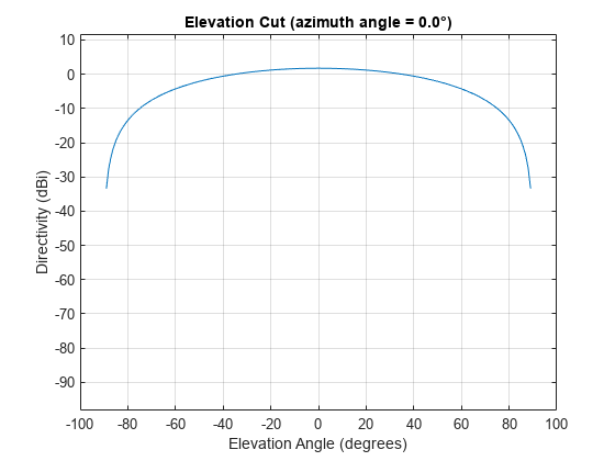
Plot an elevation cut of the directivity as a line plot, showing that the maximum directivity is approximately 2 dB.
pattern(antenna,fc,0,[-90:90],'CoordinateSystem','rectangular', ... 'Type','directivity')
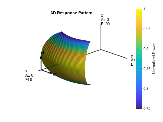
Create a custom antenna System object™. The user-defined pattern is omnidirectional in the azimuth direction and has a cosine pattern in the elevation direction. Assume the antenna operates at a frequency of 1 GHz. First show the response at boresight. Display the 3-D pattern for a 60 degree range of azimuth and elevation angles centered at 0 degrees azimuth and 0 degrees elevation in 0.1 degree increments.
fc = 1e9; azang = -180:180; elang = -90:90; magpattern = mag2db(repmat(cosd(elang)',1,numel(azang))); antenna = phased.CustomAntennaElement('AzimuthAngles',azang, ... 'ElevationAngles',elang,'MagnitudePattern',magpattern); resp = antenna(fc,[0;0])
resp =
1
Plot the power pattern for a range of angles.
pattern(antenna,fc,[-30:0.1:30],[-30:0.1:30],'CoordinateSystem','polar', ...
    'Type','power')
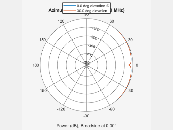
Create an antenna with a custom response. The user-defined pattern has a sine pattern in the azimuth direction and a cosine pattern in the elevation direction. Assume the antenna operates at a frequency of 500 MHz. Plot an azimuth cut of the power pattern of the custom antenna element at 0 and 30 degrees elevation. Assume the operating frequency is 500 MHz.
Create the antenna element.
fc = 500e6;
antenna = phased.CustomAntennaElement;
antenna.AzimuthAngles = -180:180;
antenna.ElevationAngles = -90:90;
antenna.MagnitudePattern = mag2db(abs(cosd(antenna.ElevationAngles)'*sind(antenna.AzimuthAngles)));
patternAzimuth(antenna,fc,[0 30],'Type','powerdb')

Plot a reduced range of azimuth angles using the Azimuth parameter.
patternAzimuth(antenna,fc,[0 30],'Azimuth',[-45:45],'Type','powerdb')
Create an antenna with a custom response. The user-defined pattern has a sine pattern in the azimuth direction and a cosine pattern in the elevation direction. Assume the antenna operates at a frequency of 500 MHz. Plot an elevation cut of the power of the custom antenna element at 0 and 30 degrees elevation. Assume the operating frequency is 500 MHz.
Create the antenna element.
fc = 500e6;
antenna = phased.CustomAntennaElement;
antenna.AzimuthAngles = -180:180;
antenna.ElevationAngles = -90:90;
antenna.MagnitudePattern = mag2db(abs(cosd(antenna.ElevationAngles)'*sind(antenna.AzimuthAngles)));
patternElevation(antenna,fc,[0 30],'Type','powerdb')

Plot a reduced range of elevation angles using the Azimuth parameter.
patternElevation(antenna,fc,[0 30],'Elevation',[-45:45],'Type','powerdb')

Algorithms
The total response of a custom antenna element is a combination
of its frequency response and spatial response. phased.CustomAntennaElement calculates
both responses using nearest neighbor interpolation, and then multiplies
the responses to form the total response.
Extended Capabilities
Usage notes and limitations:
pattern,patternAzimuth,patternElevation, andplotResponsemethods are not supported.See System Objects in MATLAB Code Generation (MATLAB Coder).
Version History
Introduced in R2011a
MATLAB Command
You clicked a link that corresponds to this MATLAB command:
Run the command by entering it in the MATLAB Command Window. Web browsers do not support MATLAB commands.
选择网站
选择网站以获取翻译的可用内容,以及查看当地活动和优惠。根据您的位置,我们建议您选择:。
您也可以从以下列表中选择网站:
如何获得最佳网站性能
选择中国网站(中文或英文)以获得最佳网站性能。其他 MathWorks 国家/地区网站并未针对您所在位置的访问进行优化。
美洲
- América Latina (Español)
- Canada (English)
- United States (English)
欧洲
- Belgium (English)
- Denmark (English)
- Deutschland (Deutsch)
- España (Español)
- Finland (English)
- France (Français)
- Ireland (English)
- Italia (Italiano)
- Luxembourg (English)
- Netherlands (English)
- Norway (English)
- Österreich (Deutsch)
- Portugal (English)
- Sweden (English)
- Switzerland
- United Kingdom (English)