directivity
Directivity of antenna or transducer element
Description
D = directivity(element,FREQ,ANGLE)element, at frequencies specified by FREQ in direction
angles specified by ANGLE.
Input Arguments
Antenna or transducer element, specified as a Phased Array System Toolbox System object.
Frequencies for computing directivity and patterns, specified as a positive scalar or 1-by-L real-valued row vector. Frequency units are in hertz.
For an antenna, microphone, or sonar hydrophone or projector element,
FREQmust lie within the range of values specified by theFrequencyRangeorFrequencyVectorproperty of the element. Otherwise, the element produces no response and the directivity is returned as–Inf. Most elements use theFrequencyRangeproperty except forphased.CustomAntennaElementandphased.CustomMicrophoneElement, which use theFrequencyVectorproperty.For an array of elements,
FREQmust lie within the frequency range of the elements that make up the array. Otherwise, the array produces no response and the directivity is returned as–Inf.
Example: [1e8 2e6]
Data Types: double
Angles for computing directivity, specified as a 1-by-M real-valued
row vector or a 2-by-M real-valued matrix, where M is
the number of angular directions. Angle units are in degrees. If ANGLE is
a 2-by-M matrix, then each column specifies a direction
in azimuth and elevation, [az;el]. The azimuth
angle must lie between –180° and 180°. The elevation
angle must lie between –90° and 90°.
If ANGLE is a 1-by-M vector,
then each entry represents an azimuth angle, with the elevation angle
assumed to be zero.
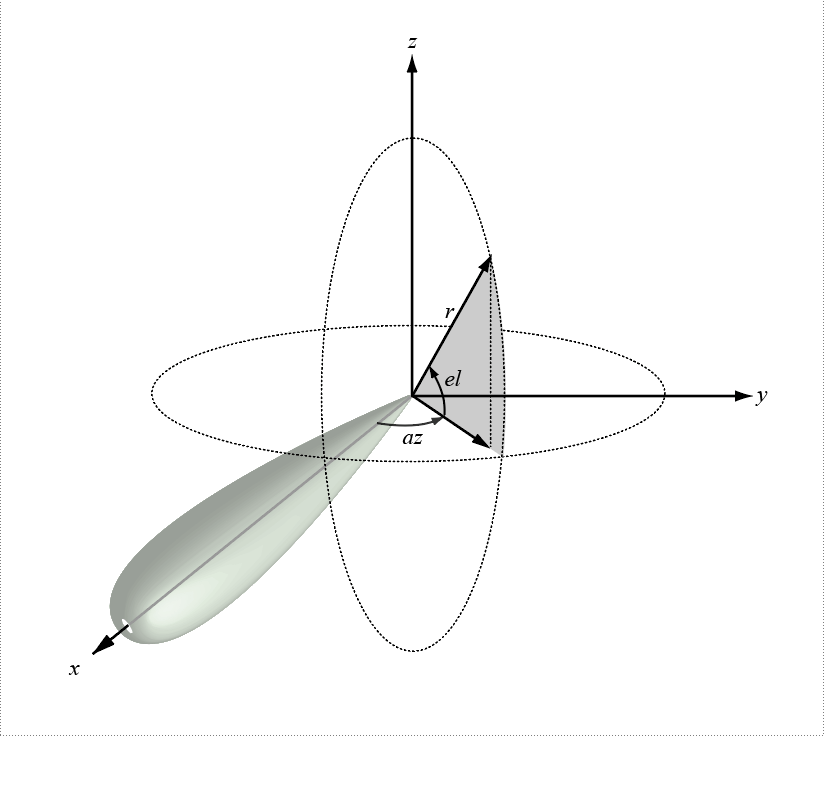
The azimuth angle is the angle between the x-axis and the projection of the direction vector onto the xy plane. This angle is positive when measured from the x-axis toward the y-axis. The elevation angle is the angle between the direction vector and xy plane. This angle is positive when measured towards the z-axis. See Azimuth and Elevation Angles.
Example: [45 60; 0 10]
Data Types: double
Output Arguments
More About
Directivity describes the directionality of the radiation pattern of a sensor element or array of sensor elements.
Higher directivity is desired when you want to transmit more radiation in a specific direction. Directivity is the ratio of the transmitted radiant intensity in a specified direction to the radiant intensity transmitted by an isotropic radiator with the same total transmitted power
where Urad(θ,φ) is the radiant intensity of a transmitter in the direction (θ,φ) and Ptotal is the total power transmitted by an isotropic radiator. For a receiving element or array, directivity measures the sensitivity toward radiation arriving from a specific direction. The principle of reciprocity shows that the directivity of an element or array used for reception equals the directivity of the same element or array used for transmission. When converted to decibels, the directivity is denoted as dBi. For information on directivity, read the notes on Element Directivity and Array Directivity.
The azimuth angle of a vector is the angle between the x-axis and the orthogonal projection of the vector onto the xy-plane. The angle is positive from the x-axis toward the y-axis. Azimuth angles lie between –180 and 180 degrees. The elevation angle is the angle between the vector and its orthogonal projection onto the xy-plane. The angle is positive toward the positive z-axis from the xy-plane. By default, the boresight direction of an element or array is aligned with the positive x-axis. The boresight direction is the direction of the main lobe of an element or array.
Note
The elevation angle is sometimes defined as the angle a vector makes with the positive z-axis. The MATLAB® and Phased Array System Toolbox products do not use this definition.
This figure illustrates the azimuth and elevation angles of a direction vector.

Version History
Introduced in R2019a
See Also
MATLAB Command
You clicked a link that corresponds to this MATLAB command:
Run the command by entering it in the MATLAB Command Window. Web browsers do not support MATLAB commands.
选择网站
选择网站以获取翻译的可用内容,以及查看当地活动和优惠。根据您的位置,我们建议您选择:。
您也可以从以下列表中选择网站:
如何获得最佳网站性能
选择中国网站(中文或英文)以获得最佳网站性能。其他 MathWorks 国家/地区网站并未针对您所在位置的访问进行优化。
美洲
- América Latina (Español)
- Canada (English)
- United States (English)
欧洲
- Belgium (English)
- Denmark (English)
- Deutschland (Deutsch)
- España (Español)
- Finland (English)
- France (Français)
- Ireland (English)
- Italia (Italiano)
- Luxembourg (English)
- Netherlands (English)
- Norway (English)
- Österreich (Deutsch)
- Portugal (English)
- Sweden (English)
- Switzerland
- United Kingdom (English)