phased.CustomMicrophoneElement
Custom microphone element
Description
The CustomMicrophoneElement
System object™ models a microphone element with a custom spatial response pattern.
To compute the response of the microphone element for specified directions:
Create the
phased.CustomMicrophoneElementobject and set its properties.Call the object with arguments, as if it were a function.
To learn more about how System objects work, see What Are System Objects?
Creation
Syntax
Description
microphone = phased.CustomMicrophoneElementmicrophone, with default object properties.
microphone = phased.CustomMicrophoneElement(Name=Value)microphone, with each specified
property set to the specified value. You can specify additional name-value pair arguments
in any order as
(Name1=Value1,...,NameN=ValueN).
Example: microphone = phased.CustomMicrophoneElement(FrequencyVector=[0
1000],FrequencyResponse=[0 -10],PolarPatternFrequencies=[100 1000]) creates a
custom microphone element with its frequency response specified at 0 and 1000 Hz. The
frequency response at these frequencies is 0 and -10 dB. The pattern frequencies are 100
and 1000 Hz.
Properties
Usage
Description
RESP = microphone(FREQ,ANG)RESP, at frequencies
specified in FREQ and directions specified in
ANG.
Note
The object performs an initialization the first time the object is executed. This
initialization locks nontunable properties
and input specifications, such as dimensions, complexity, and data type of the input data.
If you change a nontunable property or an input specification, the System object issues an error. To change nontunable properties or inputs, you must first
call the release method to unlock the object.
Input Arguments
Output Arguments
Object Functions
To use an object function, specify the
System object as the first input argument. For
example, to release system resources of a System object named obj, use
this syntax:
release(obj)
Examples
Construct a custom cardioid microphone with an operating frequency of 700 Hz. Find the microphone response in the directions: (0,0) degrees azimuth and elevation and (40,50) degrees azimuth and elevation.
microphone = phased.CustomMicrophoneElement;
microphone.PolarPatternFrequencies = [500 1000];
microphone.PolarPattern = mag2db([ ...
    0.5+0.5*cosd(microphone.PolarPatternAngles); ...
    0.6+0.4*cosd(microphone.PolarPatternAngles)]);
fc = 700;
ang = [0 0; 40 50]';
resp = microphone(fc,ang)
resp = 2×1

    1.0000
    0.7424
Create a custom cardioid microphone, and calculate the microphone response at 500, 1500, and 2000 Hz in two directions: (0,0) azimuth and elevation, and (40,50) azimuth and elevation. Then display the microphone pattern.
microphone = phased.CustomMicrophoneElement( ...
    PolarPatternFrequencies=[500 1000]);
microphone.PolarPattern = mag2db([...
    0.5+0.5*cosd(microphone.PolarPatternAngles);...
    0.6+0.4*cosd(microphone.PolarPatternAngles)]);
Obtain the microphone response in two directions.
resp = microphone([500 1500 2000],[0 0; 40 50]')
resp = 2×3

    1.0000    1.0000    1.0000
    0.7424    0.7939    0.7939
Display the microphone power pattern.
pattern(microphone,500,-180:180,0,'Type','powerdb')

Compute the directivity of a custom microphone element. Create a custom cardioid microphone, and plot the microphone's response at 700 Hz for elevations between -90 and +90 degrees.
Define the pattern for the custom microphone element. The System object's PolarPatternAngles property has default value of [-180:180] degrees.
myAnt = phased.CustomMicrophoneElement;
myAnt.PolarPatternFrequencies = [500 1000];
myAnt.PolarPattern = mag2db([...
    0.5+0.5*cosd(myAnt.PolarPatternAngles);...
    0.6+0.4*cosd(myAnt.PolarPatternAngles)]);
Calculate the directivity as a function of elevation at zero degrees azimuth.
elev = [-90:5:90];
azm = zeros(size(elev));
ang = [azm;elev];
freq = 700;
d = directivity(myAnt,freq,ang);
plot(elev,d)
xlabel('Elevation (deg)')
ylabel('Directivity (dBi)')
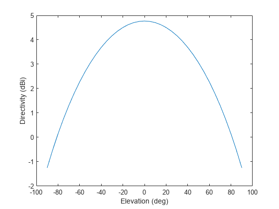
The directivity is maximum at elevation.
Show that the phased.CustomMicrophoneElement microphone element does not support polarization.
microphone = phased.CustomMicrophoneElement;
isPolarizationCapable(microphone)
ans = logical
   0
The returned value 0 shows that the custom microphone element does not support polarization.
Design a cardioid microphone to operate in the frequency range between 500 and 1000 Hz.
sCustMike = phased.CustomMicrophoneElement;
sCustMike.PolarPatternFrequencies = [500 1000];
sCustMike.PolarPattern = mag2db([...
    0.5+0.5*cosd(sCustMike.PolarPatternAngles);...
    0.6+0.4*cosd(sCustMike.PolarPatternAngles)]);
Display a polar plot of an azimuth cut of the response at 500 Hz and 1000 Hz.
fc = 500;
pattern(sCustMike,[fc 2*fc],[-180:180],0,...
    'CoordinateSystem','polar',...
    'Type','powerdb');

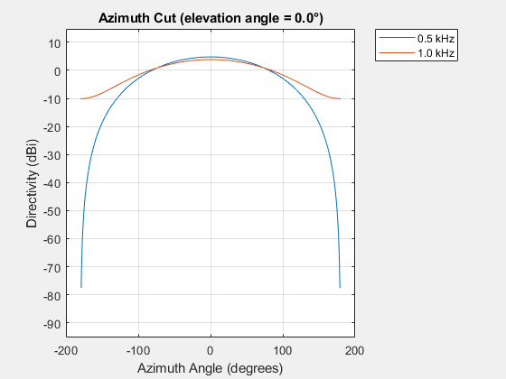
Plot the directivity as a line plot for the same two frequencies.
pattern(sCustMike,[fc 2*fc],[-180:180],0,...
    'CoordinateSystem','rectangular',...
    'Type','directivity');
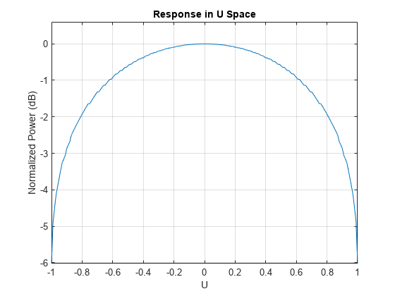
Plot a -cut of the power pattern of a custom cardioid microphone designed to operate in the frequency range 500-1000 Hz.
Create a cardioid microphone.
sCustMike = phased.CustomMicrophoneElement;
sCustMike.PolarPatternFrequencies = [500 1000];
sCustMike.PolarPattern = mag2db([...
    0.5+0.5*cosd(sCustMike.PolarPatternAngles);...
    0.6+0.4*cosd(sCustMike.PolarPatternAngles)]);
Plot the power pattern.
fc = 500;
pattern(sCustMike,fc,[-1:.01:1],0,...
    'CoordinateSystem','uv',...
    'Type','powerdb');
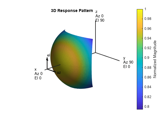
Plot the 3-D magnitude pattern of a custom cardioid microphone with both the azimuth and elevation angles restricted to the range -40 to 40 degrees in 0.1 degree increments.
Create a custom microphone element with a cardioid pattern.
sCustMike = phased.CustomMicrophoneElement;
sCustMike.PolarPatternFrequencies = [500 1000];
sCustMike.PolarPattern = mag2db([...
    0.5+0.5*cosd(sCustMike.PolarPatternAngles);...
    0.6+0.4*cosd(sCustMike.PolarPatternAngles)]);
Plot the 3-D magnitude pattern.
fc = 500;
pattern(sCustMike,fc,[-40:0.1:40],[-40:0.1:40],...
    'CoordinateSystem','polar',...
    'Type','efield');
Plot the azimuth directivity pattern of a custom cardioid microphone at both 0 and 30 degrees elevation.
Create a custom microphone element with a cardioid pattern.
sCustMike = phased.CustomMicrophoneElement;
sCustMike.PolarPatternFrequencies = [500 1000];
sCustMike.PolarPattern = mag2db([...
    0.5+0.5*cosd(sCustMike.PolarPatternAngles);...
    0.6+0.4*cosd(sCustMike.PolarPatternAngles)]);
Plot the directivity at 500 Hz.
fc = 500;
patternAzimuth(sCustMike,fc,[0 30])

Plot the directivity for a reduced range of azimuth angles using the Azimuth parameter. Notice the change in scale.
fc = 500;
patternAzimuth(sCustMike,fc,[0 30],...
    'Azimuth',[-40:.1:40])

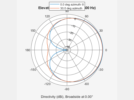
Plot the elevation directivity pattern of a custom cardioid microphone at both 0 and 45 degrees azimuth.
Create a custom microphone element with a cardioid pattern.
sCustMike = phased.CustomMicrophoneElement;
sCustMike.PolarPatternFrequencies = [500 1000];
sCustMike.PolarPattern = mag2db([...
    0.5+0.5*cosd(sCustMike.PolarPatternAngles);...
    0.6+0.4*cosd(sCustMike.PolarPatternAngles)]);
Plot the directivity at 500 Hz.
fc = 500;
patternElevation(sCustMike,fc,[0 30])
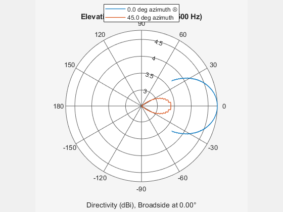
Plot the directivity for a reduced range of azimuth angles using the Azimuth parameter. Notice the change in scale.
fc = 500;
patternElevation(sCustMike,fc,[0 45],...
    'Elevation',[-40:.1:40])
Algorithms
The total response of a custom microphone element is a combination
of its frequency response and spatial response. phased.CustomMicrophoneElement calculates
both responses using nearest neighbor interpolation and then multiplies
them to form the total response. When the PolarPatternFrequencies property
value is nonscalar, the object specifies multiple polar patterns.
In this case, the interpolation uses the polar pattern that is measured
closest to the specified frequency.
Extended Capabilities
Version History
Introduced in R2011a