Wideband Beamforming
Support for Wideband Beamforming
Beamforming achieved by multiplying the sensor input by a complex exponential with the appropriate phase shift only applies for narrowband signals. In the case of wideband, or broadband, signals, the steering vector is not a function of a single frequency. Wideband processing is commonly used in microphone and acoustic applications.
Phased Array System Toolbox™ software provides conventional and adaptive wideband beamformers. They include:
See Acoustic Beamforming Using a Microphone Array for an example of using wideband beamforming to extract speech signals in noise.
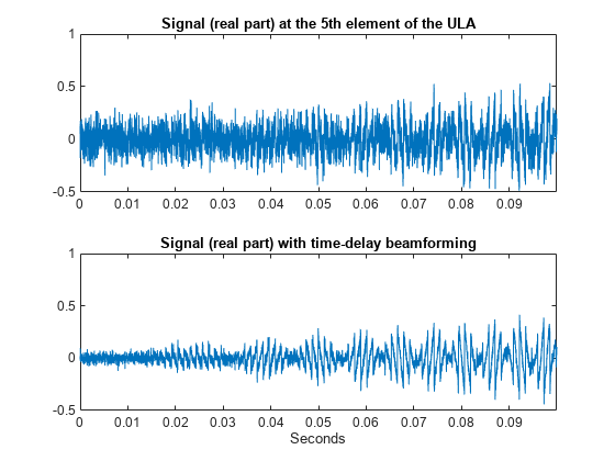
Time-Delay Beamforming of Microphone ULA Array
This example shows how to perform wideband conventional time-delay beamforming with a microphone array of omnidirectional elements. Create an acoustic (pressure wave) chirp signal. The chirp signal has a bandwidth of 1 kHz and propagates at a speed of 340 m/s at ground level.
c = 340;
t = linspace(0,1,50e3)';
sig = chirp(t,0,1,1000);
Collect the acoustic chirp with a ten-element ULA. Use omnidirectional microphone elements spaced less than one-half the wavelength at the 50 kHz sampling frequency. The chirp is incident on the ULA with an angle of azimuth and elevation. Add random noise to the signal.
microphone = phased.OmnidirectionalMicrophoneElement(...
    'FrequencyRange',[20 20e3]);
array = phased.ULA('Element',microphone,'NumElements',10,...
    'ElementSpacing',0.01);
collector = phased.WidebandCollector('Sensor',array,'SampleRate',5e4,...
    'PropagationSpeed',c,'ModulatedInput',false);
sigang = [60;0];
rsig = collector(sig,sigang);
rsig = rsig + 0.1*randn(size(rsig));
Apply a wideband conventional time-delay beamformer to improve the SNR of the received signal.
beamformer = phased.TimeDelayBeamformer('SensorArray',array,...
    'SampleRate',5e4,'PropagationSpeed',c,'Direction',sigang);
y = beamformer(rsig);

subplot(2,1,1)
plot(t(1:5000),real(rsig(1:5e3,5)))
axis([0,t(5000),-0.5,1])
title('Signal (real part) at the 5th element of the ULA')
subplot(2,1,2)
plot(t(1:5000),real(y(1:5e3)))
axis([0,t(5000),-0.5,1])
title('Signal (real part) with time-delay beamforming')
xlabel('Seconds')

Visualization of Wideband Beamformer Performance
This example shows how to plot the response of an acoustic microphone element and an array of microphone elements to validate the performance of a beamformer. The array must maintain an acceptable array pattern throughout the bandwidth.
Create an 11-element uniform linear array (ULA) of microphones using cosine antenna elements as microphones. The phased.CosineAntennaElement System object™ is general enough to be used as a microphone element as well because it creates or receives a scalar field. You need to change the response frequencies to the audible range. In addition make sure the PropagationSpeed parameter in the array pattern methods are set to the speed of sound in air.
c = 340;
freq = [1000 2750];
fc = 2000;
numels = 11;
microphone = phased.CosineAntennaElement('FrequencyRange',freq);
array = phased.ULA('NumElements',numels,...
   'ElementSpacing',0.5*c/fc,'Element',microphone);
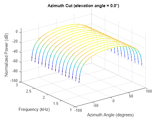
Plot the response pattern of the microphone element over a set of frequencies.
plotFreq = linspace(min(freq),max(freq),15);
pattern(microphone,plotFreq,[-180:180],0,'CoordinateSystem','rectangular',...
    'PlotStyle','waterfall','Type','powerdb')

This plot shows that the element pattern is constant over the entire bandwidth.
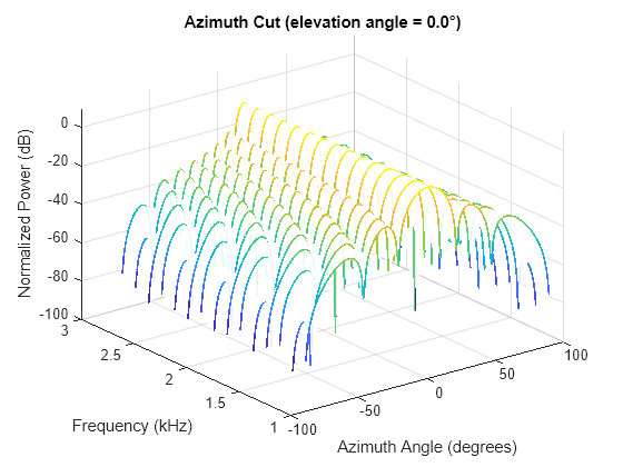
Plot the response pattern of an 11-element array over the same set of frequencies.
pattern(array,plotFreq,[-180:180],0,'CoordinateSystem','rectangular',...
    'PlotStyle','waterfall','Type','powerdb','PropagationSpeed',c)

This plot shows that the element pattern mainlobe decreases with frequency.
Apply a subband phase shift beamformer to the array. The direction of interest is 30° azimuth and 0° elevation. There are 8 subbands.
direction = [30;0];
numbands = 8;
beamformer = phased.SubbandPhaseShiftBeamformer('SensorArray',array,...
   'Direction',direction,...
   'OperatingFrequency',fc,'PropagationSpeed',c,...
   'SampleRate',1e3,...
   'WeightsOutputPort',true,'SubbandsOutputPort',true,...
   'NumSubbands',numbands);
rx = ones(numbands,numels);
[y,w,centerfreqs] = beamformer(rx);
Plot the response pattern of the array using the weights and center frequencies from the beamformer.
pattern(array,centerfreqs.',[-180:180],0,'Weights',w,'CoordinateSystem','rectangular',...
    'PlotStyle','waterfall','Type','powerdb','PropagationSpeed',c)

The above plot shows the beamformed pattern at the center frequency of each subband.
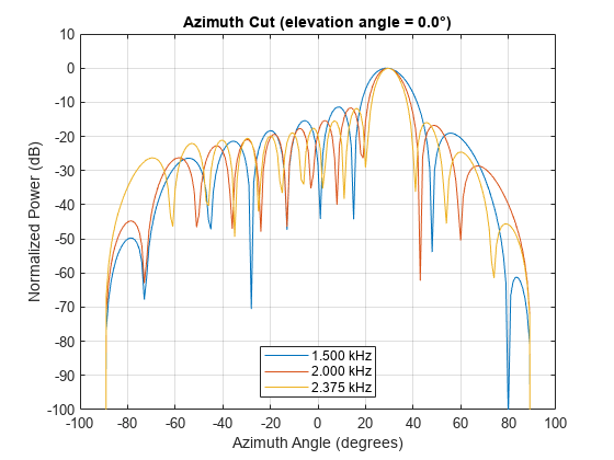
Plot the response pattern at three frequencies in two-dimensions.
centerfreqs = fftshift(centerfreqs);
w = fftshift(w,2);
idx = [1,5,8];
pattern(array,centerfreqs(idx).',[-180:180],0,'Weights',w(:,idx),'CoordinateSystem','rectangular',...
    'PlotStyle','overlay','Type','powerdb','PropagationSpeed',c)
legend('Location','South')

This plot shows that the main beam direction remains constant while the beamwidth decreases with frequency.