Raspberry Pi Camera Video Capture
R2026bRaspberry Pi Camera Video Capture block
To add a block to a model, double-click the canvas and start typing the block name. Then, select the block from the list.
Libraries:
Raspberry Pi Blockset /
Audio and Video
Description
The Raspberry Pi Camera Video Capture block captures video frames from a camera serial interface (CSI) on Raspberry Pi® hardware and outputs the image data as separate color panes. Use this block to capture live camera data within your Simulink® model for vision and image processing workflows on Raspberry Pi hardware.
Tune the camera output for your application using the image and device controls such as brightness, contrast, saturation, sharpness, exposure mode and compensation, white balance mode, metering mode, rotation, and region of interest (ROI).
During simulation, the block outputs a moving test-pattern image to support model development without hardware. When you run the model on Raspberry Pi, the block captures live video frames from the connected CSI camera module.
Note
To generate C/C++ code for this block, you must have an Embedded Coder® license.
Examples
This example shows how to capture live video from a Raspberry Pi CSI‑connected camera module using thee Raspberry Pi Camera Video Capture block and display the video frames in Simulink.
Create a new Simulink model and add the Raspberry Pi Camera Video Capture block from the Raspberry Pi Blockset > Audio and Video library.
Open the block parameter dialog box. Set Image
size to 640x480 and Pixel
format to RGB.
Set Sample
time to 0.1 to capture frames at 10 frames per second
(fps).
Add three Display (Simulink) blocks to the model. Connect the R, G, and B output ports of the Raspberry Pi Camera Video Capture block to the three Display blocks, respectively.
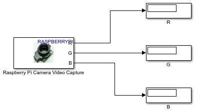
On the Hardware tab of the model, set the hardware board to your target device and configure the device address. In the Mode section, select Connected IO and then click Run with IO. Observe the live camera feed.
This example shows how to adjust image properties such as brightness and exposure for a Raspberry Pi CSI camera using the Raspberry Pi Camera Video Capture block.
Create a new Simulink model and add the Raspberry Pi Camera Video Capture block from the Raspberry Pi Blockset > Audio and Video library.
Open the block parameter dialog box. Set Image
size to 640x480 and Pixel
format to RGB.
Add three Display (Simulink) blocks to the model. Connect the R, G, and B output ports of the Raspberry Pi Camera Video Capture block to the three Display blocks, respectively.
Open the Advanced tab of the block parameters. In the
Device properties section, set Exposure mode to Normal and adjust Exposure mode
compensation to 0.7 to brighten the image.
Set AWB
mode to Daylight to optimize white balance for
outdoor lighting conditions.
On the Hardware tab of the model, in the Mode section, select Connected IO and then click Run with IO. Observe the live camera feed. While the model runs, adjust the Brightness, Contrast, Saturation, and Sharpness sliders in the block dialog box to observe changes in real time.
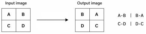
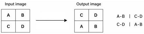
This example shows how to use the Flip image along horizontal axis and Flip image along vertical axis parameters to mirror an image horizontally and vertically by observing how pixel positions change from input to output. The following example uses a simplified 2x2 image where, each letter represents a pixel position.
This diagram shows how the block flips the input image along the vertical axis. The image pixels in each row swap positions from left to right, while row positions remain unchanged.
This diagram shows how the block flips the input image along the horizontal axis. The image rows swap positions from top to bottom, while column positions remain unchanged.
Extended Examples
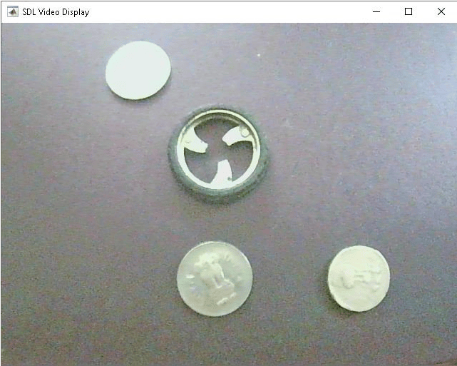
Configure Image and Device Properties of Raspberry Pi V4L2 Video Capture Block to Detect Objects
Configure the image and device properties of the V4L2 Video Capture block from Raspberry Pi® Blockset and observe the output in the SDL Video Display block. This example also shows how to tune the image properties of the V4L2 Video Capture block to detect objects in a noisy and distorted real-time video.
Ports
Output
Parameters
Extended Capabilities
Version History
Introduced in R2026b

