Run SIL and PIL Verification for Reinforcement Learning
This example shows how to perform software-in-the-loop (SIL) and processor-in-the-loop (PIL) verification workflows for reinforcement learning agents in Simulink®.
Prerequisites
This example requires the following hardware.
Raspberry Pi® hardware.
Wi-Fi® dongle or an Ethernet cable.
Power source and cable for the Raspberry Pi hardware.
You must also download and install the following support packages using the Add-Ons Explorer.
Raspberry Pi® Blockset™. See Get Started with Raspberry Pi Blockset (Raspberry Pi Blockset) for more information about how to install the support package and set up your Raspberry Pi hardware.
MATLAB® Coder™ Interface for Deep Learning. This will install the Intel® MKL-DNN and ARM® Compute libraries.
Simulink Environment
The environment for this example is a Quanser QUBE™-Servo 2 pendulum swing-up model. The controller for this environment is a reinforcement learning policy that computes the actions to swing up and balance the pendulum. For details about the environment and controller design, see the Train Default TD3 Agent to Control Quanser QUBE Pendulum example.

Open the Simulink model.
mdl = "rlQubeServo_SIL_PIL";
open_system(mdl)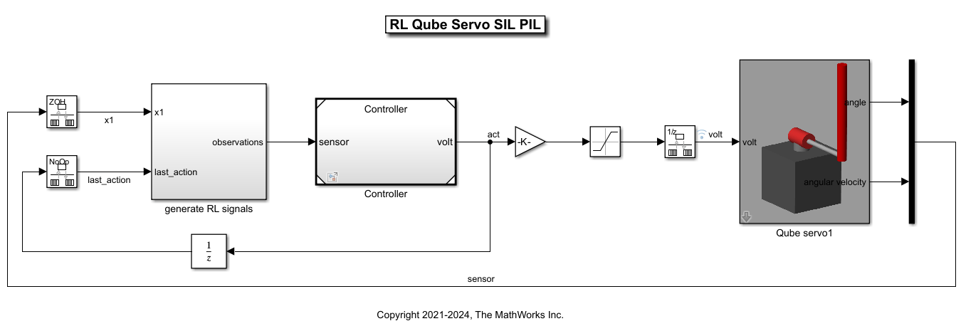
Load the model configuration settings into the MATLAB workspace. These settings will be used for SIL and PIL simulations.
load("configs.mat")Define the limit for ( radians), (3zero radians/second), voltage limit (12 volts), as well as the agent's sample time (0.005 seconds).
theta_limit = 5*pi/8;
dtheta_limit = 30;
volt_limit = 12;
Ts = 0.005;
Define the initial conditions for ( radians),(zero radians),( radians),(zero radians).
theta0 = -pi/6;
dtheta0 = 0;
phi0 = pi;
dphi0 = 0;
The Controller model reference consists of a Policy block that evaluates a trained reinforcement learning policy. The block is generated using the RL Agent option.
Open and view the Controller system.
open_system("Controller");
Greedy Policy Block Generation
The example is already configured with the greedy policy block, but you can regenerate the block using the following steps:
Open the Train Default TD3 Agent to Control Quanser QUBE Pendulum example and run the example Live Script.
From the Simulink model, open the RL Agent block dialog.
Click Generate greedy policy block.
Replace the Policy block in
Controller.slxwith the generated block. Save the model.Copy over the generated MAT file
(blockAgentData.mat)to the working directory of this example.

Software-in-the-Loop Simulation
You can analyze code generation performance using software-in-the-loop (SIL) simulation. A SIL simulation generates and builds code on your development computer and then simulates the system using the generated code. You can then compare the results with a Normal mode simulation.
Configure Controller Model for SIL Simulation
Configure the Controller model reference for code generation using pre-defined settings.
setActiveConfigSet("Controller","configSILReferenceRL");
To configure the model yourself:
Open the
Controller.slxmodel.In the Simulink model window, on the Modeling tab, click Model Settings.
In the Configuration Parameters window, in the Solver section, set the Type parameter to
Fixed-stepand Solver parameter todiscrete. Set the Fixed-step size parameter toTs, which is 0.005 s.In the Simulation Target section, set the Language parameter to
C++and the Target Library parameter toMKL-DNN. If using the Deep Learning Toolbox Predict block for evaluation, set Language toC.In the Code Generation section, set the System target file parameter to
ert.tlcand the Language parameter toC. Also, select an appropriate Toolchain parameter.Optionally, you can set the Language to
C++and set the Target library in the Code Generation > Interface section to MKL-DNN. Doing so generates C++ code for the controller.Save the model.
Optionally, you can view the generated code for the controller from the C-code perspective.
In the Simulink model window, on the Apps tab, in the gallery, click Embedded Coder.
To generate code and display it in the Code panel, on the C Code tab, click Build.
Ensure that there are no errors in this process. You can reconfigure the code generation settings to optimize the generated code.
Configure Top-Level Model for SIL Simulation
Specify the simulation mode for the Controller model reference in the top-level model rlQubeServo_SIL_PIL.slx.
set_param("rlQubeServo_SIL_PIL/Controller", ...
    SimulationMode="Software-in-the-loop (SIL)")
Alternately, right-click the Controller subsystem and select Block Parameters. Then, in the Block Parameters dialog box, set the Simulation mode parameter to Software-in-the-loop (SIL).

Run SIL Simulation
Fix the random seed for reproducibility.
rng(0,"twister");To run the SIL simulation:
In the top-level model, on the Apps tab, click SIL/PIL Manager.
On the SIL/PIL tab, in the System Under Test drop-down menu, select
Model blocks in SIL/PIL mode.Then, in the Top Model Mode, select
Normal.To simulate the model, generate and run the code in a SIL simulation, and compare the results, click Run Verification. The results are shown in the Simulink Data Inspector.

A comparison of the logged volt signal is shown between Normal and SIL simulations. The error tolerance of 1e-3 is acceptable for this example.

Processor-in-the-Loop Simulation
In a processor-in-the-loop (PIL) simulation, you can generate code for the target hardware (in this case the Raspberry Pi), and deploy and run the code from the hardware. The results of the PIL simulation are transferred to Simulink to verify the numerical equivalence of the simulation and the code generation results. The PIL verification process is an important part of the design cycle to ensure that the behavior of the deployment code matches the design.
Setup Raspberry Pi Hardware
Install the required add-ons and set up the Raspberry Pi hardware as per instructions in the Prerequisites section.
Connect the Raspberry Pi to the host computer and power it on.
Replace the information in the code below with the logon credentials of your hardware.
Execute the
raspi(Raspberry Pi Blockset) command to ensure that the hardware is connected.
ipaddress ="172.31.28.34"; username =
"pi"; password =
"raspberry"; mypi = raspi(ipaddress, username, password)
mypi =
  raspi with properties:

         DeviceAddress: '172.31.28.34'
                  Port: 18734
             BoardName: 'Raspberry Pi 2 Model B'
         AvailableLEDs: {'led0'}
  AvailableDigitalPins: [4,5,6,12,13,14,15,16,17,18,19,20,21,22,23,24,25,26,27]
  AvailableSPIChannels: {'CE0','CE1'}
     AvailableI2CBuses: {'i2c-1'}
      AvailableWebcams: {}
           I2CBusSpeed: 100000
AvailableCANInterfaces: {}

  Supported peripherals
Configure Controller Model for PIL Simulation
Configure the Controller model reference for code generation using pre-defined settings.
setActiveConfigSet("Controller","configPILReference");
To configure the model yourself:
Open the
Controller.slxmodel.In the Simulink model window, on the Modeling tab, click Model Settings.
In the Configuration Parameters window, in the Solver section, set the Type parameter to
Fixed-stepand Solver parameter todiscrete. Set the Fixed-step size parameter toTs, which is 0.005 s.In the Simulation Target section, set the Language parameter to
C++and the Target Library parameter toMKL-DNN. If using the Deep Learning Toolbox Predict block for evaluation, set Language toC.In the Code Generation section, set the System target file parameter to
ert.tlcand the Language parameter toC.Select an appropriate Toolchain parameter. The GNU GCC Embedded Linux toolchain was selected for this example.
Optionally, you can set the Language to
C++and set the Target library in the Code Generation > Interface section to MKL-DNN. Doing so generates C++ code for the controller.Save the model.
In the Configuration Parameters window, under the Hardware Implementation section:
Set the Hardware board parameter to
Raspberry Pi.Under Target hardware resources enter the board parameters. Specify the Device Address, Username, and Password as parameters to appropriate values.
Save the model.
Configure Top-Level Model for PIL Simulation
Specify the simulation mode for the Controller model reference in the top-level model rlQubeServo_SIL_PIL.slx.
set_param("rlQubeServo_SIL_PIL/Controller", ...
    SimulationMode="Processor-in-the-loop (PIL)")
Alternatively, open the top-level model rlQubeServo_SIL_PIL.slx. Then, right-click the Controller subsystem and select Block Parameters. In the Block Parameters dialog box, set the Simulation mode parameter to Processor-in-the-loop (PIL).

Run PIL Simulation
Fix the random seed for reproducibility.
rng(0,"twister");To run the PIL simulation:
In the top-level model, on the Apps tab, click SIL/PIL Manager.
On the SIL/PIL tab, in the System Under Test drop-down menu, select
Model blocks in SIL/PIL mode.Then, in the Top Model Mode, select
Normal.To simulate the model, generate and run the code on the hardware, and compare the results, click Run Verification. The results are shown in the Simulink Data Inspector.

A comparison of controller output values is shown between Normal and PIL simulations. The error tolerance of 1e-3 is acceptable for this example.

See Also
Functions
raspi(Raspberry Pi Blockset) |generatePolicyBlock
Objects
Blocks
Topics
- Train Default DDPG Agent to Swing Up and Balance Continuous Pendulum
- Train Default TD3 Agent to Control Quanser QUBE Pendulum
- SIL and PIL Simulations (Embedded Coder)
- Reinforcement Learning Workflow
- Examine Approaches to Fine Tune a Deployed Policy
- Generate Code from Trained Reinforcement Learning Policies
- Build and Deploy Your First Simulink Model to Raspberry Pi (Raspberry Pi Blockset)