Main Content

rf.Filter

Filter complex baseband RF signals

Since R2024b

Description

Use the rf.Filter System object™ to filter complex baseband RF signals in MATLAB. You can use the Butterworth, Chebyshev, or inverse Chebyshev design methods to design your filter. You can also model your RF filter in the time or frequency domain.

To filter complex baseband RF signals:

  1. Create the rf.Filter object and set its properties.

  2. Call the object with arguments, as if it were a function.

To learn more about how System objects work, see What Are System Objects?

Creation

Description

rffilt = rf.Filter creates an idealized filter that allows you to filter complex baseband RF signals.

example

rffilt = rf.Filter(Name=Value) sets properties of the rf.Filter object using one or more name-value arguments. For example, rffilt = rf.Filter(DesignMethod='Chebyshev') creates an idealized amplifier Chebyshev filter. Properties you do not specify retain their default values.

Properties

expand all

Unless otherwise indicated, properties are nontunable, which means you cannot change their values after calling the object. Objects lock when you call them, and the release function unlocks them.

If a property is tunable, you can change its value at any time.

For more information on changing property values, see System Design in MATLAB Using System Objects.

Filter Type, Response, and Order

Filter design method, specified as one of the following:

  • Butterworth

  • Chebyshev

  • InverseChebyshev

Filter response type, specified as one of the following:

  • Lowpass — Simulates a lowpass filter with the design specified in the DesignMethod property.

  • Highpass — Simulates a highpass filter with the design specified in the DesignMethod property.

  • Bandpass — Simulates a bandpass filter with the design specified in the DesignMethod property.

  • Bandstop — Simulates a bandstop filter with the design specified in the DesignMethod property.

Option to set the filter order manually, specified as a logical 1(true) or 0 (false).

Filter order, specified as a real finite nonnegative integer greater than 2. If you set ResonseType to:

  • Lowpass or Highpass — Filter order must equal to the number of lumped storage elements.

  • Bandpass or Bandstop — Filter order must be twice the number of lumped storage elements.

Dependencies

To enable this property, set UseFilterOrder to 1(true).

Passband Frequencies

Passband frequency for the lowpass filter, specified as a positive real scalar in Hz.

Dependencies

To enable this property, set ResponseType to Lowpass.

Passband frequency for the highpass filter, specified as a positive real scalar in Hz.

Dependencies

To enable this property, set ResponseType to Highpass.

Passband frequency for the bandpass filter, specified as a positive ascending two-tuple vector in Hz.

Dependencies

To enable this property, set ResponseType to Bandpass.

Passband frequency for the bandstop filter, specified as a positive ascending two-tuple vector in Hz.

Dependencies

To enable this property, set ResponseType to Bandstop.

Stopband Frequencies

Stopband frequency for the lowpass filter, specified as a positive real scalar in Hz.

Dependencies

To enable this property, set ResponseType to Lowpass and set UseFilterOrder to 0 (false).

Stopband frequency for the highpass filter, specified as a positive real scalar in Hz.

Dependencies

To enable this property, set ResponseType to Highpass and set UseFilterOrder to 0 (false).

Stopband frequency for the bandpass filter, specified as a positive ascending two-tuple vector in Hz.

Dependencies

To enable this property, set ResponseType to Bandpass and set UseFilterOrder to 0 (false).

Stopband frequency for the bandstop filter, specified as a positive ascending two-tuple vector in Hz.

Dependencies

To enable this property, set ResponseType to Bandstop and set UseFilterOrder to 1 (true).

Passband and Stopband Attenuation

Passband attenuation of the filter, specified as a positive real scalar in dB. For bandpass filters,the System object applies this value equally to both edges of the passband.

Dependencies

To enable this property, set ResponseType to Lowpass, Highpass, or Bandpass.

Stopband attenuation, specified as a positive real scalar greater than the PassAtten value in dB.

Dependencies

To enable this parameter, you can either:

  • Set ResponseType to Lowpass, Highpass, or Bandpass and set UseFilterOrder to 0 (false).

  • Set ResponseType to Bandstop and set UseFilterOrder to 1 (true).

Signal Parameters

Carrier frequency of the complex baseband modulated signal or the signal bandwidth with respect to the filter transfer function, specified as a positive real scalar in Hz. The signal bandwidth is1Simulink Step Size .

Sample rate of the input complex baseband signal, specified as a nonnegative real scalar of data type double in samples per second.

Dependencies

To enable this property, set IncludeNoise to true.

Usage

Description

out = rffilt(in) returns a filtered time-dependent output signal out based on the input baseband signal in.

Input Arguments

expand all

Time-dependent input signal, specified as a real scalar, real column, complex scalar, or complex column. A column represents consecutive points in time.

Data Types: double | single

Output Arguments

expand all

Time-dependent output signal, returned as a complex scalar or complex column. The output time-dependent signal is equal in size to the input time-dependent signal.

Data Types: double | single

Object Functions

To use an object function, specify the System object as the first input argument. For example, to release system resources of a System object named obj, use this syntax:

release(obj)

expand all

visualizeVisualize idealized amplifier characteristics, S-parameter data, and filter response
stepRun System object algorithm
releaseRelease resources and allow changes to System object property values and input characteristics
resetReset internal states of System object

Examples

collapse all

Generate a 16-QAM signal.

in = qammod(randi([0 15],1000,1),16,'UnitAveragePower',true);

Filter the 16-QAM signal using the rf.Filter System object.

rffilt = rf.Filter;
out = rffilt(in);

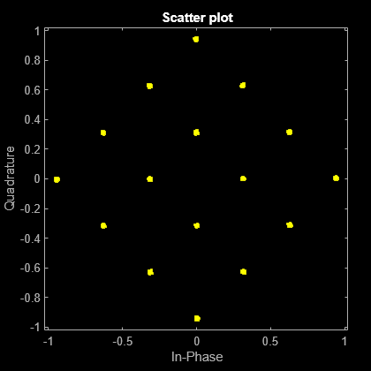
Plot the filtered output.

scatterplot(out)

Figure Scatter Plot contains an axes object. The axes object with title Scatter plot, xlabel In-Phase, ylabel Quadrature contains a line object which displays its values using only markers. This object represents Channel 1.

Version History

Introduced in R2024b