Execute Tasks for a Warehouse Robot
This example demonstrates how to execute an obstacle-free path for a mobile robot between three locations on a given map. The robot is expected to visit the three locations in a warehouse: a charging station, loading station, and unloading location. The sequence in which these locations are visited is dictated by a scheduler. The scheduler gives each robot a goal pose to navigate to. The robot plans a path and uses a Pure Pursuit controller to follow the waypoints based on the current pose of the robot. The Differential Drive Kinematic Model block models the simplified kinematics, which takes the linear and angular velocities from the Pure Pursuit Controller. This example builds on top of the Plan Path for a Differential Drive Robot in Simulink example.
Warehouse Map
A typical warehouse of a sorting or distribution facility has packages to be delivered from work stations to storage areas. The warehouse may have off-limit areas like offices and in-progress inventory blocking aisles or walkways. The robots are tasked with picking finished packages as they arrive at the sorting station and are told a location to store them. The warehouse also has a charging station for recharging the robots after a certain time.

This sample warehouse floor-plan can be translated into a binary occupancy map, which indicates all the safe regions in the warehouse facility.
Load the example map file. logicalMap is a matrix of logical values indicating free space in the warehouse. Make a binaryOccupancyMap from this matrix.
load warehouseMaps.mat logicalMap
map = binaryOccupancyMap(logicalMap);
show(map)
Assign the xy-locations of the charging station, sorting (loading) station, and the unloading location near shelves in the warehouse.
chargingStn = [5,5];
loadingStn = [52,15];
unloadingStn = [15,42];
Show the various locations on the map.
hold on;

text(chargingStn(1), chargingStn(2), 1, 'Charging');
plotTransforms([chargingStn, 0], [1 0 0 0])

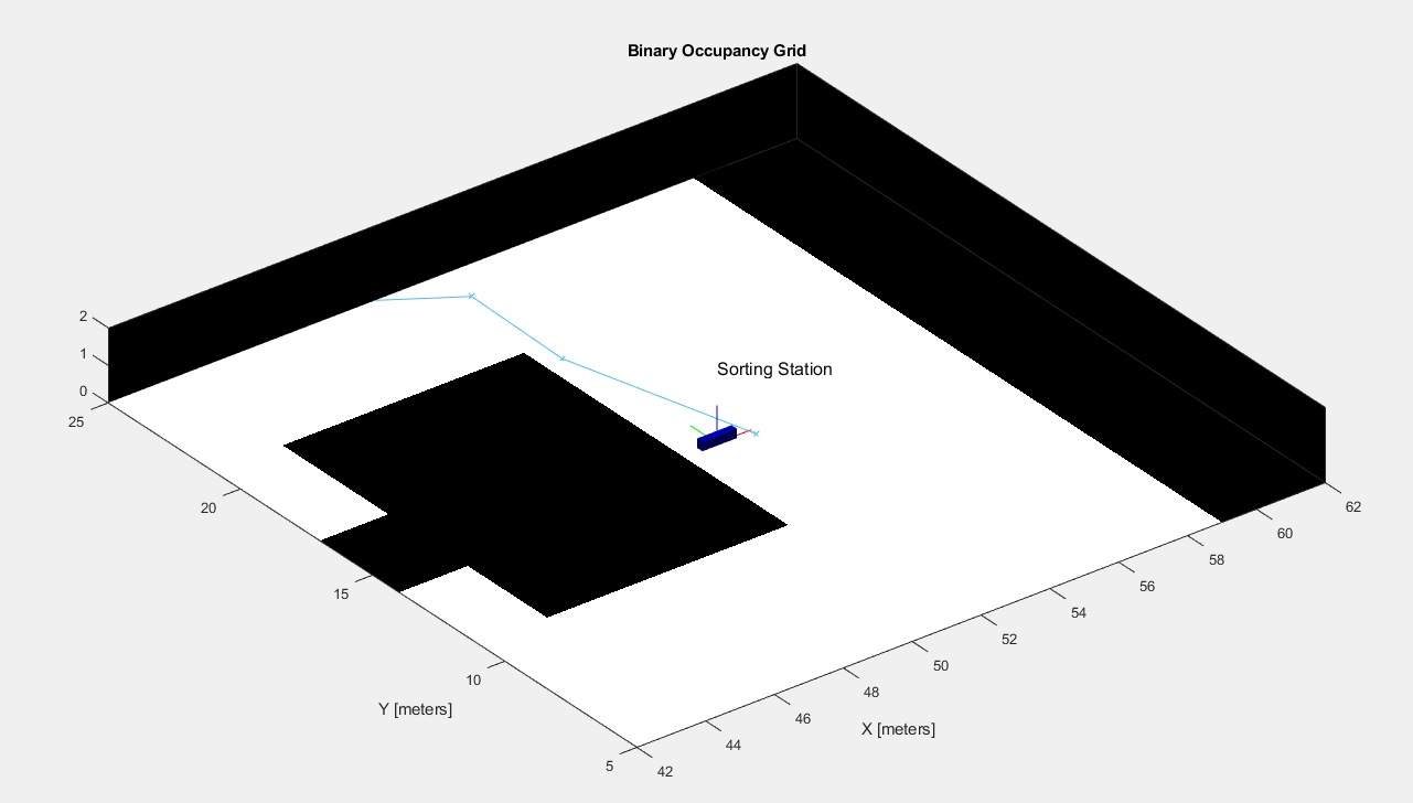
text(loadingStn(1), loadingStn(2), 1, 'Sorting Station');
plotTransforms([loadingStn, 0], [1 0 0 0])

text(unloadingStn(1), unloadingStn(2), 1, 'Unloading Station');
plotTransforms([unloadingStn, 0], [1 0 0 0])

hold off;
![Figure contains an axes object. The axes object with title Binary Occupancy Grid, xlabel X [meters], ylabel Y [meters] contains 16 objects of type patch, line, image, text.](../../examples/robotics/win64/ExecuteTasksForAWarehouseRobotExample_02.png)
Model Overview
A Simulink® model is provided that models all aspects of the system for scheduling, planning, controlling, and modeling the robot behavior.
Open the Simulink Model.
open_system('warehouseTasksRobotSimulationModel.slx')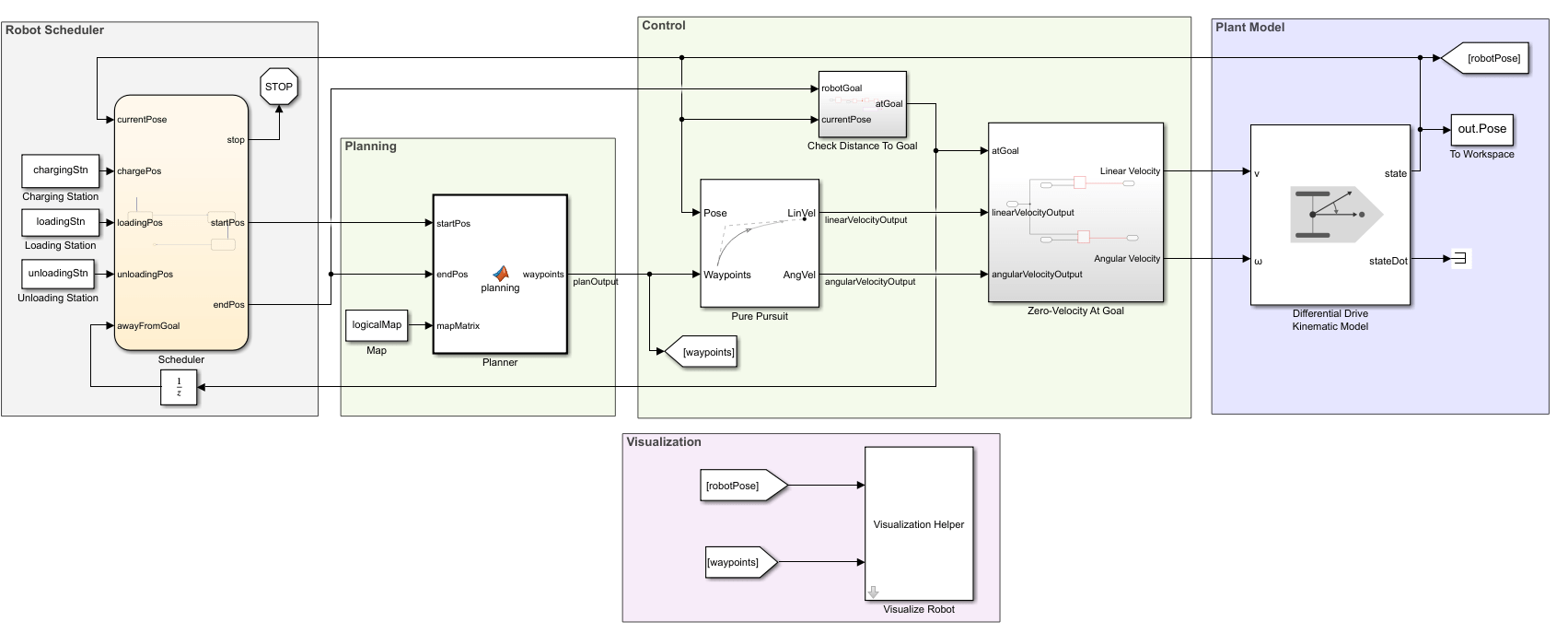
Planning, Control, and Plant Model
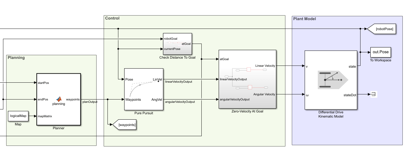
The model uses a planning, control, and plant model similar to the Plan Path for a Differential Drive Robot in Simulink example. The planner takes the start and goal locations from the scheduler and plans an obstacle-free path between them based on the given map. The controller uses a Pure Pursuit controller for generating the linear and angular velocity controls of the robot to navigation the path. These controls are given to the plant model that models the behavior of a differential-drive robot.
Robot Scheduler
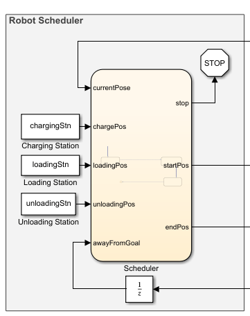
The Scheduler block assigns start and goal locations to the robot. The current pose of the robot is used as a starting location and the end location is determined by a sequence of tasks specified inside the scheduler. The example illustrates the following sequence of tasks for the robot:
Starts from the charging location, and goes to the loading location.
Pauses as the loading station to load the package and plans a path to the unloading location.
Navigates to the unloading station to unload the package. Replans a path to the charging station.
Stops at the charging station.
Simulate the Robot
Run the simulation to see the robot execute the tasks.
simulation = sim('warehouseTasksRobotSimulationModel.slx');![Figure contains an axes object. The axes object with title Binary Occupancy Grid, xlabel X [meters], ylabel Y [meters] contains 21 objects of type patch, line, image, text.](../../examples/robotics/win64/ExecuteTasksForAWarehouseRobotExample_06.png)
Visualize Robot Trajectories
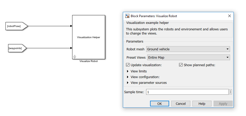
A custom visualization tool is given to mimic a distributed camera system and get more detailed views of the robot trajectory at certain locations in the map. Open the Visualization Helper block and use the Preset Views drop-down to select different perspectives. The Sample time of the visualization has no effect on the simulation of the robot.

See Also
© Copyright 2019 The MathWorks, Inc.