Perform Path Planning Simulation with Mobile Robot
Create a scenario to simulate a mobile robot navigating a room. The example demonstrates how to create a scenario, model a robot platform from a rigid body tree object, obtain a binary occupancy grid map from the scenario, and plan a path for the mobile robot to follow using the mobileRobotPRM path planning algorithm.
Create Scenario with Ground Plane and Static Meshes
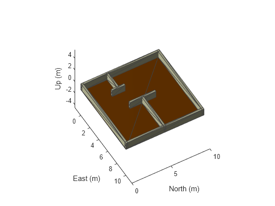
A robotScenario object consists of a set of static obstacles and movable objects called platforms. Use robotPlatform object to model the mobile robot within the scenario. This example builds a scenario consisting of a ground plane and box meshes to create a room.
scenario = robotScenario(UpdateRate=5);
Add a plane mesh as ground plane in the scenario.
floorColor = [0.5882 0.2941 0];
addMesh(scenario,"Plane",Position=[5 5 0],Size=[10 10],Color=floorColor);
The walls of the room are modeled as box meshes. The static meshes are added with the IsBinaryOccupied value set to true, so these obstacles are incorporated into the binary occupancy map used for path planning.
wallHeight = 1;
wallWidth = 0.25;
wallLength = 10;
wallColor = [1 1 0.8157];

% Add outer walls.
addMesh(scenario,"Box",Position=[wallWidth/2, wallLength/2, wallHeight/2],...
    Size=[wallWidth, wallLength, wallHeight],Color=wallColor,IsBinaryOccupied=true);
addMesh(scenario,"Box",Position=[wallLength-wallWidth/2, wallLength/2, wallHeight/2],...
    Size=[wallWidth, wallLength, wallHeight],Color=wallColor,IsBinaryOccupied=true);
addMesh(scenario,"Box",Position=[wallLength/2, wallLength-wallWidth/2, wallHeight/2],...
    Size=[wallLength, wallWidth, wallHeight],Color=wallColor,IsBinaryOccupied=true);
addMesh(scenario,"Box",Position=[wallLength/2, wallWidth/2, wallHeight/2],...
    Size=[wallLength, wallWidth, wallHeight],Color=wallColor,IsBinaryOccupied=true);

% Add inner walls.
addMesh(scenario,"Box",Position=[wallLength/8, wallLength/3, wallHeight/2],...
    Size=[wallLength/4, wallWidth, wallHeight],Color=wallColor,IsBinaryOccupied=true);
addMesh(scenario,"Box",Position=[wallLength/4, wallLength/3, wallHeight/2],...
    Size=[wallWidth, wallLength/6,  wallHeight],Color=wallColor,IsBinaryOccupied=true);
addMesh(scenario,"Box",Position=[(wallLength-wallLength/4), wallLength/2, wallHeight/2],...
   Size=[wallLength/2, wallWidth, wallHeight],Color=wallColor,IsBinaryOccupied=true);
addMesh(scenario,"Box",Position=[wallLength/2, wallLength/2, wallHeight/2],...
    Size=[wallWidth, wallLength/3, wallHeight],Color=wallColor,IsBinaryOccupied=true);
Visualize the scenario.
show3D(scenario);
lightangle(-45,30);
view(60,50);

Obtain Binary Occupancy Map from Scenario
Obtain an occupancy map as a binaryOccupancyMap object from the scenario for path planning. Inflate the occupied spaces on the map by 0.3m.
map = binaryOccupancyMap(scenario,GridOriginInLocal=[-2 -2],...
                                           MapSize=[15 15],...
                                           MapHeightLimits=[0 3]);
inflate(map,0.3);
Visualize the 2-D occupancy map.
show(map)
![Figure contains an axes object. The axes object with title Binary Occupancy Grid, xlabel X [meters], ylabel Y [meters] contains an object of type image.](../../examples/robotics/win64/PerformPathPlanningSimulationWithMobileRobotExample_02.png)
Path Planning
Use the mobileRobotPRM path planner to find an obstacle-free path between the start and goal positions on the obtained map.
Specify the start and goal positions of the mobile robot.
startPosition = [1 1];
goalPosition = [8 8];
Set the rng seed for repeatability.
rng(100)
Create a mobileRobotPRM object with the binary occupancy map and specify the maximum number of nodes. Specify the maximum distance between the two connected nodes.
numnodes = 2000;
planner = mobileRobotPRM(map,numnodes);
planner.ConnectionDistance = 1;
Find a path between the start and goal positions.
waypoints = findpath(planner,startPosition,goalPosition);
Trajectory Generation
Generate trajectory for the mobile robot to follow with the waypoints from the planned path using the waypointTrajectory System object™.
% Robot height from base.
robotheight = 0.12;
% Number of waypoints.
numWaypoints = size(waypoints,1);
% Robot arrival time at first waypoint.
firstInTime = 0;
% Robot arrival time at last waypoint.
lastInTime = firstInTime + (numWaypoints-1);
% Generate waypoint trajectory with waypoints from planned path.
traj = waypointTrajectory(SampleRate=10,...
                          TimeOfArrival=firstInTime:lastInTime, ...
                          Waypoints=[waypoints, robotheight*ones(numWaypoints,1)], ...
                          ReferenceFrame="ENU");
Add Robot Platform to Scenario
Load the Clearpath Husky mobile robot from the robot library as a rigidBodyTree object.
huskyRobot = loadrobot("clearpathHusky");Create a robotPlatform object with the robot model specified as a rigidBodyTree object and its trajectory specified as a waypointTrajectory System object.
platform = robotPlatform("husky",scenario, RigidBodyTree=huskyRobot,...
                         BaseTrajectory=traj);
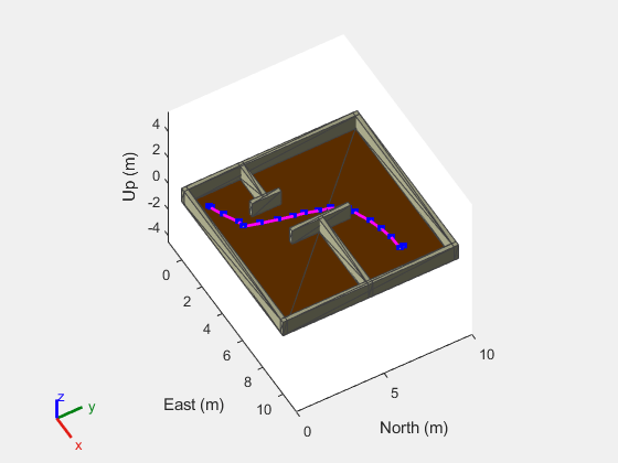
Visualize the scenario with the robot.
[ax,plotFrames] = show3D(scenario);
lightangle(-45,30)
view(60,50)

Simulate Mobile Robot
Visualize the planned path.
hold(ax,"on")
plot(ax,waypoints(:,1),waypoints(:,2),"-ms",...
               LineWidth=2,...
               MarkerSize=4,...
               MarkerEdgeColor="b",...
               MarkerFaceColor=[0.5 0.5 0.5]);
hold(ax,"off")
Set up the simulation. Since all the poses of the robot are known in advance, simply step through the simulation and update the visualization at each step.
setup(scenario)

% Control simulation rate at 20 Hz.
r = rateControl(20);

% Status of robot in simulation.
robotStartMoving = false;

while advance(scenario)
    show3D(scenario,Parent=ax,FastUpdate=true);
    waitfor(r);

    currentPose = read(platform);
    if ~any(isnan(currentPose))
        % implies that robot is in the scene and performing simulation.
        robotStartMoving = true;
    end
    if any(isnan(currentPose)) && robotStartMoving
        % break, once robot reaches goal position.
        break;
    end
end

To re-run the simulation and visualize the results again, reset the simulation in the scenario.
restart(scenario)