Getting Started with Connecting and Controlling a UR5e Cobot from Universal Robots Using RTDE Interface
This example shows how to use the urRTDEClient object to connect to a Universal Robots cobot and move the robot using joint space control, task space control, waypoint tracking in task space, and waypoint tracking in joint space. This example uses Robotics System Toolbox™ Support Package for Universal Robots UR Series Manipulators.
By default, the example uses the Universal Robots UR5e cobot model to simulate the behavior. You can choose between URSim simulator or UR hardware to run this example.
This example uses the functionalities offered by the urRTDEClient object to connect with simulated or physical cobot using the TCP network. Once the connection is established with the cobot, you can use various object functions of urRTDEClient to manipulate the cobot.
Clear all output in the live script by right-clicking anywhere in the live script and then clicking ‘Clear All Output’ or navigate to VIEW > Clear all Output.
Note: Execute the script section by section as mentioned in this example.
Required Products
Robotics System Toolbox™
Robotics System Toolbox™ Support Package for Universal Robots UR Series Manipulators
Prerequisites
Complete initial setup to establish communication between MATLAB® and URSim or between MATLAB® and UR Series hardware. For more information, see Set Up URSim Offline Simulator for RTDE or Set Up UR Series Cobot for RTDE.
Initialize urRTDEClient Interface
Specify the IP address of UR controller and the cobot name.
ur = urRTDEClient('192.168.75.138','CobotName','universalUR5e')
ur =
  urRTDEClient with properties:

            CobotName: 'universalUR5e'
       URControllerIP: '192.168.75.138'
    ControllerVersion: '5.16.0.0'
        RTDEFrequency: 125
    ConnectionTimeOut: 10
        RigidBodyTree: [1×1 rigidBodyTree]
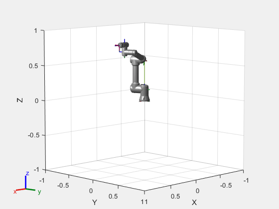
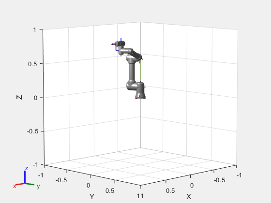
The urRTDEClient object has several useful properties. The CobotName property contains the name of the rigid body tree model required to be loaded. This is used internally for trajectory generation and motion planning for the Cartesian pose to joints estimation. You can use ur.RigidBodyTree.show() to visualize the robot manipulator in MATLAB. The RTDEFrequency sets the frequency at which data is sampled and exchanged between the MATLAB Client and UR Control server.
Read Various Robot State Data
Read current joint angle configuration with a timeout of 10 seconds. The readJointConfiguration function returns the current joint angle of the cobot in the range of -2pi to 2pi. The order of the joints is similar to the rigid body tree model.
jointAngles = readJointConfiguration(ur)
jointAngles = 1×6

    0.3491   -1.5708   -1.2217   -0.3491    1.2217         0
Show the robot in current joint configuration
show(ur.RigidBodyTree,jointAngles)

ans =
  Axes (Primary) with properties:

             XLim: [-1 1]
             YLim: [-1 1]
           XScale: 'linear'
           YScale: 'linear'
    GridLineStyle: '-'
         Position: [0.1300 0.1100 0.7750 0.8150]
            Units: 'normalized'

  Show all properties
Read current end-effector pose
The readCartesianPose function returns current cartesian pose of the end-effector in the form of [thetaz thetay thetax X Y Z] with units [rad rad rad m m m].
pose = readCartesianPose(ur)
pose = 1×6

   -1.5708    0.0000   -1.5708    0.4915    0.0008    0.8213
Read the current velocity of each joint
The readJointVelocity function returns current joint angle velocity of the manipulator. The unit is rad/s.
jointVelocity = readJointVelocity(ur)
jointVelocity = 1×6

     0     0     0     0     0     0
Read the current end-effector velocity
The readEndEffectorVelocity method returns the velocity of the end-effector in the form of [theta_dotz theta_doty theta_dotx Vx Vy Vz] with units [rad/s rad/s rad/s m/s m/s m/s].
eeVelocity = readEndEffectorVelocity(ur)
eeVelocity = 1×6

     0     0     0     0     0     0
Control the UR5e Cobot
Joint Space Control
Command the robot to reach to desired joint configuration and wait for the robot to complete the motion
The expected input to sendJointConfigurationAndWait function is desired joint configuration in the range of -pi to pi for all six joints. It also accepts an optional argument EndTime in seconds, The cobot tries to complete the motion from current joint configuration to desired joint configuration within the specified EndTime. The default value of EndTime is 5 seconds.
This method has a blocking function call and it waits for the robot to complete the motion. The result is 'true' if the robot motion has been completed successfully and 'false' otherwise. The state output contains more information about the status of the robot motion.
jointWaypoints = [0 -90 0 -90 0 0]*pi/180;
[result,state] = sendJointConfigurationAndWait(ur,jointWaypoints,'EndTime',5) %#ok<ASGLU>
result = logical
   1
state =
'Succeeded'
Command the robot to reach to desired joint configuration
The expected input to sendJointConfiguration method is a desired joint configuration in the range of -pi to pi for all six joints. It also accepts an optional argument EndTime in seconds, The cobot tries to complete the motion from current joint configuration to desired joint configuration within the specified EndTime. The default value of EndTime is 5 seconds.
jointWaypoints = [20 -90 -70 -20 70 0]*pi/180;
Visualize the robot in desired joint angle configuration
show(ur.RigidBodyTree,jointWaypoints);

Command the cobot to move to desired joint angle configuration.
sendJointConfiguration(ur,jointWaypoints,'EndTime',5);Wait for the robot to complete the motion
[result,~] = readMotionStatus(ur);
while ~result
    [result,~] = readMotionStatus(ur);
end
Task Space Control
Command the cobot to reach to desired cartesian pose and wait for the robot to complete the motion
The expected input to sendCartesianPoseAndWait function is desired end-effector pose in the form of [thetaz thetay thetax X Y Z]. It also accepts an optional argument EndTime in seconds, The cobot tries to complete the motion from current pose to the desired pose within the specified EndTime. The default value of EndTime is 5 seconds.
This method has a blocking function call and it waits for the cobot to complete the motion. The result will be 'true' if the cobot motion has been completed successfully and 'false' otherwise. The state output contains more information about the status of the cobot motion.
desPos = [-pi/2  0  -pi/2 0.5    0    0.8];
[result,state] = sendCartesianPoseAndWait(ur,desPos,'EndTime',2)
result = logical
1
state =
'Succeeded'
Task Space Waypoint Tracking
Command robot to follow desired set of task waypoints
The expected input to followCartesianWaypoints function is a set of cartesian waypoints and the time from start to reach each waypoint. The cartesian waypoints are interpolated internally using the minjerkpolytraj to move the cobot.
taskWayPoints = [-pi/2    0  -pi/2 0.5     0  0.5;
                 -pi/4    0  -pi/2 0.5   0.3  0.6;
                 -pi/2    0  -pi/2 0.5     0  0.8;
                 -3*pi/4  0  -pi/2 0.5  -0.3  0.6;
                 -pi/2    0  -pi/2 0.5     0  0.5];

wayPointTimes = [0 2 4 6 8];

% Follows the trajectory with specified waypoint times
followCartesianWaypoints(ur,taskWayPoints,'WaypointTimes',wayPointTimes);

% Uncomment below line to follow a smooth trajectory using default A and V
% followCartesianWaypoints(ur, taskWayPoints, 'BlendRadius', 0.02)
Joint Space Waypoint Tracking
Command robot to follow desired set of joint waypoints
The followJointWaypoints function enables the cobot to pass through the specified set of joint waypoints. The expected input to followJointWaypoints is joint position, and the waypoint times for the robot motion.
jointwayPoints = [-20 -85 110 150 -70 0;
                  -10 -70  80 200 -70 0;
                    0 -40  90 270 -70 0;
                  -10 -70  80 200 -70 0;
                  -20 -85 110 150 -70 0;]*pi/180;

waypointTimes = [0 2 4 6 8];

% Plan a trajectory for jointwayPoints
samplePoints = 20;
[q,~,~,~,~,~,~] = minjerkpolytraj(jointwayPoints', waypointTimes, samplePoints);

% Follow the planned trajectory for smooth motion using blend radius
followJointWaypoints(ur, q, 'BlendRadius', 0.02);

% Record robotstate
duration = 10; % sec
rate = 2; % hz
data = recordRobotState(ur, duration, rate);
Plot the recorded information
The recordRobotState function records the joint configuration along with pose and other vital information. Below is a sample script to view the positions plotted against the planner and actual motion on the cobot.
Note: It is important to note that the effect of controller is visible in the graph and you need to plan accordingly.
%% Extract the recorded joint configurations
recordedJointConfig = data.JointConfiguration;

% Create a figure with 6 subplots for each joint angle
figure;

for jointIdx = 1:6
    subplot(3, 2, jointIdx); % Create a 3x2 grid of subplots
    hold on;

    % Plot the recorded joint configuration for the current joint
    plot(recordedJointConfig(:, jointIdx), 'b-', 'DisplayName', ['Recorded Joint ', num2str(jointIdx)]);

    % Plot the planned trajectory for the current joint
    plot(q(jointIdx, :), 'r-o', 'DisplayName', ['Planned Joint ', num2str(jointIdx)]);

    % Add labels and legend
    xlabel('Index');
    ylabel('Joint Angle (rad)');
    legend;
    title(['Joint ', num2str(jointIdx), ' Configuration']);

    hold off;
end
Move the cobot in Joint space using ServoJ and SpeedJ commands
sendServoJCommands(ur,jointconfig) commands the Universal Robots cobot connected through RTDE interface, based on the specified joint configuration.
The gain parameter works the same way as the P-term of a PID controller, where it adjusts the current position towards the desired position. The higher the gain, the faster will be the cobot's reaction. The parameter 'LookAheadTime' is used to project the current position forward in time with the current velocity. A low value gives fast reaction, a high value prevents overshoot.
jointWaypoints = [0.0,-1.57,-1.57,0,0,3.14];
sendServoJCommands(ur, jointWaypoints, "LookAheadTime",0.05, "PGain",500)
sendSpeedJCommand(ur,jointVelocities) accelerates the cobot linearly in joint space and continue with constant joint speed. The EndTime argument is optional; if specified, the function will return after EndTime, regardless of the target speed has been reached. If the EndTime is not provided, the function will return when the target speed is reached.
% Moves the wrist3 joint at a constant velocity
jointVelocities = [0.1 0 0 0 0 0];
sendSpeedJCommands(ur,jointVelocities);
Clear the object.
clear ur